Import ODB++ Files
Import/Export 2D/EDA FilesODB++ 2D/EDA FilesODB++
The ODB++ database format has been developed
by Valor Computerized Systems Ltd. (now Mentor Graphics Corporation) in
order to facilitate the data transfer involved in PCB manufacturing processes.
In addition to etch and drill geometrical data (as in Gerber output),
further aspects of the PCB design are covered, among others:
Nets, with references to etch shapes/pinsLayer stack-upComponents (pins, name ("Refdes"), and reference
to part number)Part descriptions
ODB++ databases are organized as a multilevel directory
tree on disk. When generating the database, the option of compressing
this directory (into ".zip" or ".tgz" archives) should
be enabled. The import algorithm un-compresses the directory tree on the
fly.
The following PCB design software products support
ODB++ output:
Please check whether your layout software has the
ODB++ -generation option installed.
General
remark: If you encounter problems creating ODB++ data (e.g. the
ODB++ converter of the layout tool reports warnings or errors) please
make sure that you have successfully created Artwork data (i.e. Gerber
format RS-274D or RS-278X) previously. Then rerun the ODB++ converter.
Remark
about multiple steps: Only single-step ODB++ files can be imported,
so please delete all but the desired step, as follows: (i) Unzip the ODB++
archive on disk. (ii) In the sub-directory 'matrix', open the file 'matrix'
with a text editor. (iii) In the section 'STEP {...', delete the unwanted
steps. (iv) pack the whole ODB++ directory structure again by a standard
tool, e.g. Linux tar or Windows zip.
Remark
about R,L,C component values: Some CAD systems attach component
properties to the ODB++ output. These data are extracted into a *.csv
spreadsheet (comma-separated file) by the present ODB++ -to-CST import.
More...
When generating ODB++ output from within Mentor
Graphics庐 Expedition, the following dialog box appears.
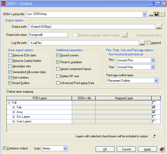
Pressing OK will generate a compressed output (*.zip
or *.gz), which can directly be imported into CST STUDIO SUITE. We recommend
choosing the above configuration. For details of the ODB++ export options,
please consult the Mentor Graphics software documentation.
Mentor Graphics庐 Boardstation
The Fablink software of the Mentor Graphics庐 Boardstation
flow supports generation of ODB++. This export extension is included in
the regular Mentor Graphics庐 Boardstation distribution free of charge.
In Fablink, choose, FileExportto ODB++..., which opens the following dialog:
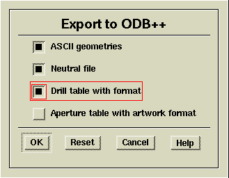
Please check the items ("ASCII geometries",
"Neutral file", and "Drill table with format") and
click "OK". The following dialog appears:
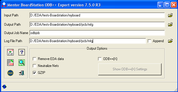
Please check the "GZIP" option. For advanced options, please consult the "Mentor
Boardstation ODB++ Export" manual. Pressing "Begin Translation"
will create the ODB++ file (here odbjob.tgz on
the given "Output Path"). You may move, copy, or rename the
created file. Giving the ".tgz" file a name related to the PCB
design is recommended (here, e.g. "myboard.tgz"), since the
3D model will carry the same name.
Zuken CR-5000
ODB++ data can be generated within the Zuken CR-5000
design flow if the associated software module has been licensed. Please
consult the Zuken software documentation for further details. However,
using the native CST interface to Zuken CR-5000
is recommended instead of using ODB++.
Cadence庐 Allegro
Please note that for Cadence庐 Allegro, the usage
of the CST-Link is recommended,
which offers more flexible selection capabilities.
If working with ODB++ is desired, the free "ODB++
Inside" software package of Mentor Graphics Corporation (http://www.mentor.com)
must be installed. In order to create the ODB++ output,
take the following steps:
Within the Cadence庐
Allegro software, choose FileExportODB++ inside. Answer
"No" when asked "Extract net impedance averages?" In
the dialog box appeared, check the "GZIP" option.
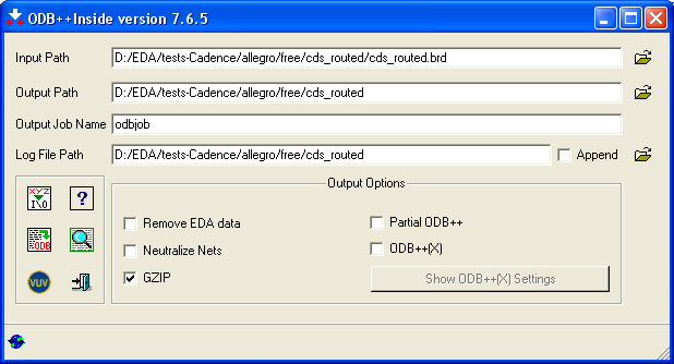
Removal
of unconnected/non-functional pads can be switched on in the advanced
options ("xyz I/O"). For
other advanced options, please consult the "ODB++ inside" manual. Pressing
"Begin Translation" will create the ODB++ file (here odbjob.tgz
on the given "Output Path"). You
may move, copy, or rename the created file. Giving the ".tgz"
file a name related to the PCB design is recommended (here, e.g. "cds_routed.tgz"),
since the 3D model will carry the same name.
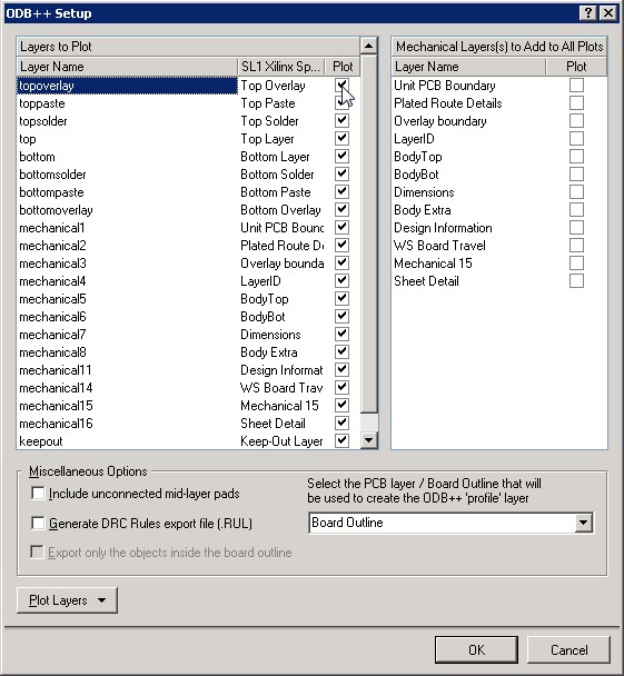
Altium Designer
Altium Designer offers the ability to export ODB++
files directly from the menu bar through 'File
Fabrication Output ODB++ Files'. If this menu item does
not exist yet, please go to 'DXP Plug-ins and updates Output Generators' , then locate and
install the 'Output - ODB' plug-in.
After clicking the menu item, the dialog below pops
up (Altium Designer 10). Please consult the Altium Designer Help for more
information. After pressing 'ok'
in the dialog, the ODB++ file is generated in the same folder as the current
PCB design. Altium will automatically open the built-in CAM-viewer, which
allows the user to review the fabrication output. (It
is not recommended to generate the ODB++ files from within the CAM viewer
(under 'File Export ODB++') as lumped
element information will be lost is this intermediate step.)
Note:
If you are experiencing problems with the generated ODB++ files, please
verify that you have the latest version of the plugin installed inside
Altium Designer.
See also
The
EDA Import Overview
Importing
and Exporting Models


HFSS视频教程
ADS视频教程
CST视频教程
Ansoft Designer 中文教程
|
