The transient co-simulation feature enables a direct transient simulation of a 3D structure including nonlinear lumped components or circuit networks. The interface between the 3D EM field simulator and the circuit simulator is facilitated by the use of discrete ports. This approach is suitable for the analysis of sub-nanosecond pulse generators, frequency multipliers with high multiplication factor, etc. An arbitrary waveform of the excitation signal can be used.
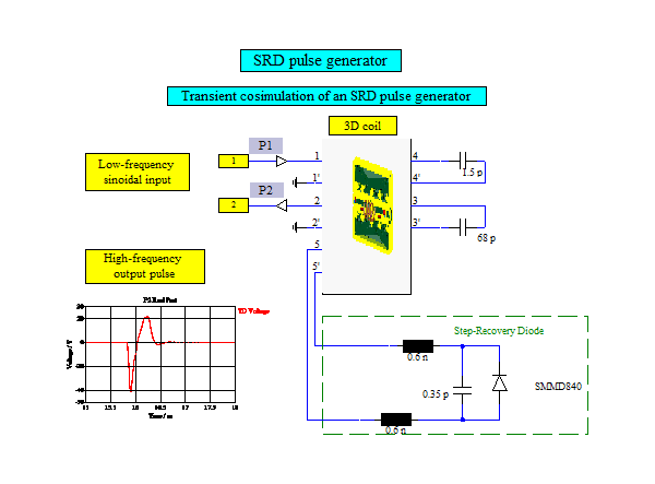
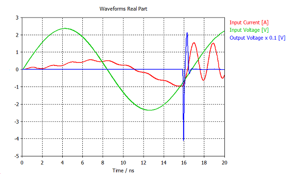
The pulse generator consists of coplanar waveguide (CPWG) layout including a helical coil, two lumped capacitors and a step-recovery diode (SRD). A spice model of the step-recovery diode SMMD840 is used which also includes the parasitic elements of the SMD package. The pulse generator is exited with a harmonic signal at 60 MHz passing through low-pass filter (capacitor 68 pF and helical coil) reaching a SRD connected in parallel. A strong non-linearity of the SRD produces a very sharp peak, which is additionally filtered by DC blocking capacitor at the output (1.5 pF).
The transient co-simulation is activated by the “MWS Co-simulation” button in the transient simulation task menu in CST DS, while the total simulation time is given by “Tmax” parameter. The input and output signals are recorded using probe P1 and probe P2 respectively. It is necessary to define differential ports of the CST MWS block in the CST DS schematic for the correct handling of differentially connected discrete ports 3,4 and 5 in the 3D model.
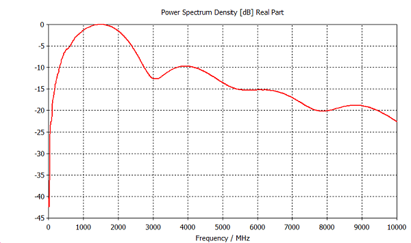
The Power Spectrum Density (PSD) of the output voltage signal can be obtained using “1D Template Based Postprocessing“ (1D Result from 1D result/PSD). It can be seen that the maximum of the PSD figure is approximately at 1500 MHz resulting in the multiplication factor of 25 (1500MHz / 60 MHz).