

The low pass' characteristics are optimized according to the goals described below. Therefore, six parameters describing the lines' width and the stubs' length are taken into consideration.
After the optimization, a final 3D simulation is performed to validate the analytical results.
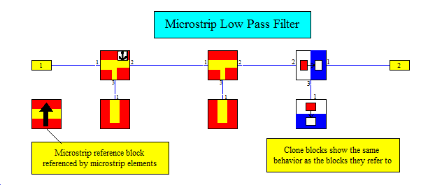
Standard microstrip blocks and clone blocks are used to build up this model. The substrate properties are defined by a reference block that all of them refer to. The following filter optimization goals for the stop band and the pass band are used:
|
Goal |
Frequency range |
|
|S21| > -0.8 dB |
0 to 4 GHz |
|
|S21| < -30 dB |
5 to 7 GHz |
The parameters' allowed variation ranges are chosen quite wide. The Optimizer may change the parameters L1 - L3 from 3 to 10, the parameters W1 - W3 from 1 to 2.5. Nevertheless, this 'brute force' optimization with the simplex algorithm by Nelder and Mead just takes around one minute on a 3.2 GHz PC. Note that there is a user-defined result plot that compares the transmissions before and after the optimization.
To validate the optimized results a simulation project is setup that performs a full 3D simulation.