A number of different parameters of a radiating body may be found with CST MICROSTRIPES:
• Directive gain: over the sphere of all directions (radiation pattern), on (great-circle) cuts and on conical cuts
• Radiation efficiency.
• Antenna efficiency.
• Antenna phase center.
• Radar Cross-Section (RCS): bistatic or monostatic.
• Near-field-cylinder-scan - this is intended for ElectroMagnetic-Compatibility (EMC) emission testing, and is the electric field (only) on a cylindrical surface centered on the radiating body. The field may be obtained both over the entire cylinder and on horizontal (circular) cuts through it.
These properties are calculated at each of up to 99 frequencies specified by the user. Additionally, it is now possible to obtain time domain output at points beyond the boundaries of the mesh. When Fourier transformed, the response at these points shows (for all frequencies) the magnitude of radiation in their particular direction.
Generally the radiation properties and the VSWR or input impedance of an antenna can be obtained from the same simulation
For a receiving antenna, it would be possible to find (say) the effective aperture by illuminating it with a plane wave and inspecting the voltage and current at its terminals. This method suffers from a number of limitations - the most obvious being that information is obtained for only one direction of illumination. The recommended approach, is to simulate the antenna as a transmitting antenna, and to infer its receiving properties by means of the reciprocity theorem.
The calculation of radiation parameters in CST MICROSTRIPES requires an equivalent surface to be positioned around the radiating structure being modelled. The equivalent surface is specified in the Build output regions window explained in Regions (frequency). Equivalent electric and magnetic surface currents are calculated on this surface by the 3D-TLM simulator at user requested frequencies. These surface currents are subsequently transformed to the near field or far field during post-processing.
The equivalent surface is also required for time domain output points outside the mesh. In this case however, the transformation is performed in the time domain, within the 3D-TLM simulator and as the simulation proceeds.
The calculation of far fields from actual surface currents is not supported as there are too many potential pitfalls (specifically; presence of dielectric or permeable materials, possibility of using incomplete data).
Consider an imaginary surface which encloses some region of space. The enclosed region may be empty or may contain any arrangement of conductive, dielectric and permeable materials, and any arrangement of electromagnetic sources. It is possible to find a distribution of electric and magnetic currents flowing on the imaginary surface, which is equivalent to all electromagnetic effects occurring in the enclosed region.The surface currents are equivalent in the sense that they would produce the same effect at any observation point outside of the enclosed region, as does the actual contents of the region. If the region were emptied and if the equivalent currents were set up, then the field outside the region would be undisturbed, while the field inside the region would be reduced to zero.
The equivalent surface currents may be determined by supposing that the field in the enclosed region was indeed reduced to zero without disturbing the external field. This would introduce a discontinuity in the tangential H-field at the boundary between the outside and inside regions, which would require a particular electric surface current. Similarly, the discontinuity in the tangential E-field would require a particular magnetic surface current. Thus, if is the outward normal to the surface, then the 3D-TLM Simulator calculates the currents

at each point on the surface (and for each frequency of interest). These currents would give rise to electric and magnetic charge distributions on the surface, and these would produce discontinuities in the normal electric and magnetic flux at the boundary.
It is simple to prove that these normal components are the same as the normal components of the original field

Thus the equivalent currents reproduce all components of the original field at the surface. In fact this is not strictly true. Because we have neglected the constants of integration, the field due to the equivalent currents could differ from the actual field by a static component normal to the surface. Such a field component might exist if there were motionless charges or bar-magnets inside the equivalent surface. However, as these components can only exist at zero frequency (and as they are radial), they do not radiate, and so their loss is of no consequence.
The main advantage of calculating the far field from equivalent surface currents rather than from actual currents, is that the effects of dielectrics, permeable materials and sources are automatically included.
A second advantage is accuracy. Integration is only used to calculate propagation from the equivalent surface outward - a differential method (TLM) is used to calculate propagation from the radiating structure out to the equivalent surface. This means that the accuracy does not depend on numerical cancellation of the effects of large currents which may be virtually enclosed in metal - such as the currents on the inside of an antenna feed.
The calculation used in the far-field transformation involves the integration of surface current and magnetic surface current. For radiation in the direction k, the integrals

are performed (where K is the wave number) and used to calculate the voltage vector:

The significance of V is that the field at a particular point a distance R in the direction k is

(+iwt convention assumed).
For the near field the transformation is similar but much more complicated.
The phase reference point is (r0 in the above integrals), is the point taken as the origin in the far-field transformation. The choice of this point determines the reported phase of the radiation in the far-field. Although this affects both the far-field cuts and the '3D' radiation pattern, it is only apparent in the cuts (since the far-field plotter does not display the absolute phase). It has no affect on the calculated magnitude of the radiation.
Points on the far field cuts are in effect a whole (though infinite) number of wavelengths from the reference point. If the reference point is placed at the phase-centre of the source, then the phase of the radiation on a cut will be found to be constant over a wide arc.
In CST MICROSTRIPES the coordinates of the phase reference point must be specified in metres, irrespective of the model-units.
When an object - a ‘target’ - is illuminated by a source or radiation, it is common to consider the resultant electromagnetic field as composed of two parts, the ‘incident’ and ‘scattered’ fields. The incident field is the field that would exist in the absence of the target and the scattered field is defined by the relation

The scattered field exactly cancels the incident field inside metal parts of the target, and approximately cancels it in any shadow regions.
The presence of the scattered field can be ascribed to currents flowing on the target (including polarization currents in any dielectric present). It is easy to see that integrating the effects of currents on the target gives the scattered field only - if there are no currents on the target, or even no target at all, we still have the incident field. Thus if there are any target currents, their effects are superposed upon this incident field.
However, it is not nearly so easy to see that the same is true for the equivalent surface currents - that their integrated effect is the scattered field only. After all, if the equivalent surface encloses nothing at all, there are still equivalent surface currents so long as there is an incident field. In this case we would be claiming that for every point outside of the surface, the effects of all these equivalent currents implausibly conspire to exactly cancel each other out (not exactly for a numerical integration of course).
Of course, we could prove this analytically, simply by taking the far field integrals, substituting into them the expressions for the equivalent currents, converting the surface integrals to volume integrals and showing that the result was equal to the integrated effect of currents inside the surface (only) - i.e. the effects of the actual target currents, which we know give the scattered field (only). While this would be a most entertaining bit of algebra, it is unnecessary as we may reach the same conclusion more simply.
We argue thus; the incident field must be due to currents flowing in some source (we make the source sufficiently far away or small or high impedance that it is not affected by back-scattered radiation from the target). Now the total field is equal to the total integrated effect of the source currents plus the actual target currents. The same total field results from the source currents plus the equivalent surface currents. So by taking away the source currents we conclude that the integrated effect of the equivalent surface currents must equal that of the actual target currents i.e. the scattered field only.
Note: When a target is illuminated from one side by a source outside of the equivalent surface, the resultant far field plot will often show a large peak in the direction of propagation of the incident field. This is not a contribution to the far field from the source. It is forward scattering by the target. Since the scattered field must be superposed on the incident field to get the total field, this peak means simply that the total field is very different from the incident field in the shadow of the target.
When there is a ground plane beneath an antenna and the ground is too extensive to be wholly enclosed by the mesh, then it is strongly recommended that the ground is modelled using a symmetry boundary (an ‘electric wall’), rather than a sheet of metal. This is because the extent of a metal ground is limited to the mesh and it will not form a complete image of the antenna. If a symmetry boundary of any sort is specified, then this information is passed to the post processing module which automatically adds in the missing half of the geometry - or in this case an exact image of the antenna.
Note that when ‘electric wall’ boundary is specified, it makes no difference whether or not there is a thin sheet of metal covering this boundary.
The use of a symmetry boundary rather than a metal sheet makes an enormous difference for antennas (such as a quarter-wave monopole) which radiate principally along the ground, and little difference for antennas which form a narrow beam going straight upward.
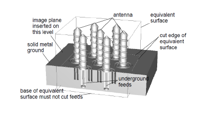
There are however many types of antenna which are fed through the ground plane, or are recessed into the ground. These sorts of underground structure make it impossible to place the ground plane on an external boundary of the mesh, and so impossible to use a symmetry boundary to form the ground image.

In order to handle these types of antenna correctly, CST MICROSTRIPES automatically detects the dangling edges of an equivalent surface where it cuts a raised ground level. The module then inserts an image plane at the appropriate level. This image plane gives an ‘electric wall’ image irrespective of the boundary condition specified for the below-ground floor of the mesh
To check that CST MICROSTRIPES has done this appropriately, check the Command Window status for the Near to Far Field module - it should say ‘<n> symmetry planes including inferred ground’ if this feature is active.
In the case of antennas fed through the ground plane, take care that the specified equivalent surface does not cut the feed (!) - if the ‘inferred ground’ is not found, this may be the cause.
An ‘inferred ground’ can erroneously be found when modelling horn antennas. This can occur when the backscattering of the antenna is not required and the feed of the horn is surrounded by a solid lossy block. This solid block serves to increase the amount of dead space in the simulation which reduces computational requirements, and is defined with a surface loss equal to that of free space, to absorb the backscattered fields. When calculating the far field pattern for such a simulation, CST MICROSTRIPES may find an ‘inferred ground’ at the ‘front’ of the solid lossy block. This can be prevented by including a two cell wide slice of living cells behind the termination of the antenna feed, and passing the back of the equivalent surface between these two cell layers.
If there are two symmetry planes (Electric or Magnetic Walls) facing each other, then reflection in these planes builds an infinite linear array of any structure that is between the planes. Such an array would only radiate in certain directions, which would be determined by the spacing of the elements. CST MICROSTRIPES will not countenance such arrays, and will issue an objection such as: ‘Error: structure infinite in x direction’.
For the full radiation pattern, the only option offered by CST MICROSTRIPES is whether to calculate on a coarse grid (1946 different directions not more than 5o apart), a fine grid (7778 directions not more than 2.5o apart), or a very fine grid (31106 directions not more than 1.25o apart).
The full pattern must be calculated in order to normalize the field on cuts or conical-cuts to dBi (dB referenced to an isotrope) or dBd (dB referenced to a (short) dipole).
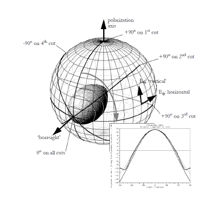
The far field cuts options are explained in the following figure. Each cut is an arc passing through the nominal forward direction or ‘boresight’ of the pattern. These are commonly called Great-Circle cuts. The far-field components on a number of these cuts are written to a single file that can be viewed with the Graph plotter. The orientation of the first cut is determined by the polarization axis, which also defines the direction of ‘vertical’ polarization. The number of cuts is determined by the requested spacing between cuts. The polarization axis and ‘boresight’ need not be perpendicular, but the module issues a warning if they are not.

The far-field on the cuts can be expressed in dB relative to the far-field on the nominal boresight (dB-boresight), or in dBi or dBd. In order to give dBi or dBd, the Near to Far module must first determine the total radiated power. This means that the cut field cannot be given in dBi or dBd unless the full radiation pattern is also calculated.
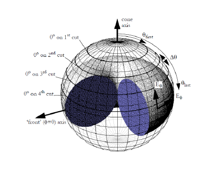
Each conical-cut is a cone of rays making an angle q with the specified cone axis. The angle f varies around each cone. The number of conical cuts is determined by the first and last values given for q and by the q-step-size.

The far-field on the conical cuts can be expressed in dBi or dBd. In order to give dBi or dBd, the Near to Far module must first determine the total radiated power. This means that to obtain the field on conical cuts, the full radiation pattern must also be calculated.
If an antenna is build from lossy materials, and if a calculation of material losses is requested, then CST MICROSTRIPES will also determine

This number, both as a percentage and in dB, is reported at the foot of the far-field plot. In addition, if scatter parameters are available for a single port device, CST MICROSTRIPES will determine

For the nominal boresight direction and nominal polarization (only), the Near to Far module examines the curvature of the far-field wavefronts. In the general case, the wavefronts will be spheroidal rather than spherical, i.e. they will be more curved in one plane and flatter in another. The planes of least and greatest curvature (principal curvature planes), and the centers of curvature in these planes are written to a file with the extension .focus.txt.
This file may be inspected using any text-editor, and appears as shown in the following example

The SCS of a body may be found by creating a model of the body, illuminating it with a plane wave and obtaining far field, or transformed field, output.
After the 3D simulation is complete, the mean scattering cross-section [SCS] is given in the key below the far field plot. This is the mean over all directions, i.e. it relates the total re-radiated power to the incident power density. It's referred to as the SCS rather than the RCS because it's for all polarizations.
The illuminating plane wave direction and polarization is indicated by an orange antenna icon in the far field plot.
As the mouse is moved over the plot, the bistatic RCS for the direction under the mouse is shown in the footer of the plotter window (or if this window is maximized, then in the footer of the main CST MICROSTRIPES window). This cross-section is for the plotted polarization only.
For each polarization requested for far field cuts, the bistatic RCS is also given. The default boresight axis is back towards the source of the illumination, so that the monostatic RCS is found at 0 deg on each cut.