In CST MICROSTRIPES a model may have one or more ports defined on it. Any port or ports may be used to excite the model, i.e. to inject a signal, and the ingoing and outgoing signals on each port will be monitored and used in determining the scattering parameters of the model.
Ports in CST MICROSTRIPES; now fall into one of two fundamental categories: waveguide-and-transmission-line-ports, or wire-ports.
At present it is not possible to attach a port inside a lumped-component circuit. It is however possible to place a wire-port on a wire leading to a circuit (provided that the port is not exactly at the connection between the wire and circuit).
Build presents the user with choice of specific types of port, namely: ‘Rectangular (TE)’, ‘Circular (TE)’, ‘Coax’, ‘Microstrip’, ‘Stripline’, ‘Co-planar’, ‘Slotline’, ‘Wire’ and ‘Other’. With the exception of ‘Wire’ these are fundamentally similar, but Build to some extent automates the setting-up of the port according to the specific guide geometry.
A port may be placed at any cross-section of a guide or line carrying a TE or TEM mode. The given cross-section becomes the reference plane of the port. A number of ports may be placed at the same cross-section (on the same physical port), but attached to different modes, to model a multimode excitation
To specify a port, the user must identify the cross-section at the reference plane, and the mode of interest.
For Build to specify the mode correctly, it needs to see the entire cross-section of the guide or transmission line - even if symmetry conditions mean that only 1/2 or 1/4 of the guide will actually be used in the simulation.
For ‘Custom’ ports (such as ridge-waveguide), the user must provide a flux-path-excitation coupling to the mode of interest. For TEM modes, the coupled excitation (initial flux-path) should follow a route from the surface of one conductor to another.
The 3D-TLM Simulator extrudes the given waveguide cross-section to generate a length of guide external to the model. Into this length of guide it puts a termination, an excitation and a means of monitoring the ingoing and outgoing signals. This apparatus may be thought of as part of a network analyser attached to the model; it takes up zero volume in the model mesh, but is compressed into the reference plane. On the back (outside surface) of the reference plane, the port apparatus presents a magnetic wall to the electromagnetic fields. This outer surface is usually in dead-space and so does not interact with the electromagnetic field.

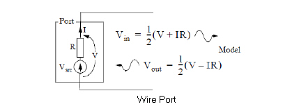
For wire ports the 3D-TLM Simulator includes the wire current I in the time-domain output, and associates with it the load impedance R. If there is a source (excitation), then the corresponding wire voltage V is also written out (otherwise it can be inferred from I). Post-processing analysis tools will subsequently recognize the wire-port in the time-domain data and determine from it (in the frequency domain) the signals entering and leaving the model through the port.
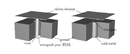
One use of wire ports is the modelling of coax feeds. If the outer coax diameter is sufficiently small (of the order of the cell-size used in the rest of the model), then the body of a coax cable may be replaced by a solid metal rod, and the protruding inner conductor replaced by a wire. A wire port of impedance equal to the characteristic impedance of the coax, is then placed on the end of the wire at the mouth of the coax.

Detailed modelling of the coax feed interior would demand a fine mesh of several cells across the diameter, and result in a small time-step. The option of dispensing with this part of the model can give a greatly reduced computer run-time. Detailed modelling is however appropriate when the feed diameter is significant.
Because there is no propagation data associated with a wire-port, it is not possible to move the port’s reference plane in the post processing tools.
In CST MICROSTRIPES for the calculation of scattering parameters, it is usually necessary to simulate a device a number of times, injecting a signal into a different port on each occasion.
The Build module offers the alternative of driving all ports in the same simulation. In this case the port excitations may be given different relative amplitudes and delays. This is appropriate for driving a phased array antenna.