 Straight
Straight
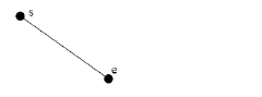
• Start point: s
• End point: e
 Arc - center
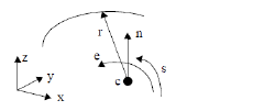
• center point: c
• Normal: n
• Radius: r
• Start angle: s
• End angle: e
The start and end angles are measured anti-clockwise when looking against the normal direction. Their values are not restricted to 0 to 360 degrees and the start angle may be greater than the end angle. Once the center, normal and reference direction have been set, the other parameters can be set by picking existing points in the model.
 Arc Through Points
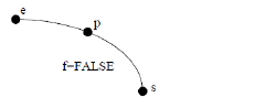
• Start point: s
• End point: e
• Third point: p
• Full circle: f
 Ellipse
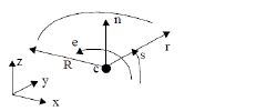
• center point: c
• Normal: n
• X radius: R
• Y radius: r
• Start angle: s
• End angle: e
This tool is used to specify the parametric definition of a curve using mathematical functions. Available operations are:
|
Laws |
|
+ - * / |
Operators: plus, minus, multiply and divide |
|
^ |
Raise the preceding expression to the power of the following one |
|
sqrt(t) |
Square root |
|
log(t) log(t, a) |
Log base 10, log base a where a is a numeric value |
|
exp(t) |
Raises e to the given power |
|
ln(t) |
Natural log |
|
pi |
3.1415926545898 |
|
cos(t) sin(t) tan (t) sec(t) csc(t) cot(t) |
Trigonometric functions: cosine, sine, tangent, secant, cosecant, cotangent
|
|
cosh(t) sinh(t) tanh(t) sech(t) csch(t) coth(t) |
Hyperbolic functions |
|
arccos(t) arcsin(t) arctan(t) arcsec(t) arccsc(t) arccot(t) |
Arc trigonometric functions |
|
arccosh(t) arcsinh(t) arctanh(t) arcsech(t) arccsch(t) arccoth(t) |
Arc hyperbolic functions |
These laws can be combined in any way to form more complex mathematical functions.
Unfortunately if the creation of a law curve fails, no real feedback is given as to the errors in the expression. When using trigonometric functions, it is better and easier to parameterize the curve between rational values and use pi in the expression than to parameterize say between 0 and 2 pi.
Care should be taken when using functions that are undefined or infinite at certain values, for example, tan (pi/2). Some examples:
A Parabola
X: t
Y: t^2 - 4
Z: 0
Range: -3 to 3
A Helix
X: 50*cos(2*pi*t)
Y: 50*sin(2*pi*t)
Z: 30*t
Range: 0 to 5
A Toroidal Coil
X: (50+10*cos(2*15*pi*t))*cos(2*pi*t)
Y: (50+10*cos(2*15*pi*t))*sin(2*pi*t)
Z: 10*sin(2*15*pi*t)
Range: 0 to 1
 Spline
Spline edges are created by specifying a list of positions that the edge is to interpolate. If four or more positions are specified then a cubic b-spline curve is created.
Pressing the Insert button adds the position with coordinates to the right of Point to the list. The point is inserted in the list after the selected point. Therefore, a new point cannot be inserted at the top of the list (the first point can be modified).
On selecting a point in the list, its coordinates are entered into the three coordinate boxes. The coordinates can then be changed and the point modified by pressing Move. The selected point can also be removed from the list with the Remove button. Error messages appear if any of the actions would result in two consecutive positions being identical.
The interpolation points appear in the viewing area as small circles and once there are two points in the list, the interpolation curve will appear. The selected point in the list is highlighted in the view.
Rather than deleting each position in the list individually, press Clear to delete all of the positions. No edge is created until the Create button is pressed.
 Curve on surface
Edges are superimposed on a curved surface through a specified point and of a specified orientation.
This tool is used to create a wire body from a list of edges. After pressing the Add/remove edges button the user can pick freestanding edges from the view to be used in the wire. The edges must be input in an order such that the edges form a continuous path. The edges may or may not form a closed loop.
The orientation of each edge does not have to be consistent. For example, it is possible to create a wire body from two straight edges that have been created with the same start point.
The resulting wire body will be made up of straight edges, but the input edges can include any other shapes. The facet tolerance can be set according to how accurately the wire should resemble the non-straight edges. The tolerance may be set between 1e-5 and 1. A rough guide to choosing the facet tolerance would be about 1% of the length of an edge.
 Wire from Points
This tool can be used to create a new wire body from a list of points or edit an existing wire by inserting additional points, moving points or deleting them.
When Create is pressed a new wire body is created from the list of points.
To modify a wire, select the name from the list at the top of the window and use the Insert, Move and Delete buttons to edit the point list, and then press Modify.
 Face from Edges
Click on Add/remove edges and pick edges to be used in the face boundary. The edges must be selected in an order that will form a continuous loop, otherwise the error message "Error [5401] in making face: Edges for wire are not connected" will appear on pressing Create.
Edges are highlighted as they are selected and the name of the edge (if it is top-level) will appear in the list. Picking a previously selected edge removes it from the list. Edges may be picked which are already used in another body; in this case the edge has no name and so ‘unnamed’ is added to the list.
The above error also occurs if the ends of the edges have gaps; the gaps should be less than 1e-6. If the edges are not connected, but do cross each other, then it may be possible to fix this problem using the edge-trimming tool.
A face can usually be created without a surface being specified. But with certain edge loops, ACIS may not be able to find a suitable surface, so use Pick surface to select an existing surface that is to be used in the face definition.

