
The S-parameters calculated for a simulated block may not refer to one single ground; they may instead be differential. Let us examine the following stripline structure to gain an understanding of what this means.
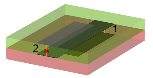
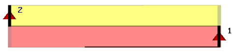
The image shows two vertically coupling striplines. Two discrete ports are defined, each located at the input/output of one line. Due to the definition of the ports according to the image below, the discrete ports are not associated with a common ground: Port No. 1 refers to the ground plane whereas port No. 2 refers to the middle line.
The description above is valid in the 3D domain. In the context of circuit simulation, it does not matter how the ports are constructed in 3D: In all cases voltages and currents need to be computed from the incoming and outgoing waves at the ports (using the n port theory). If a block port is represented with a single pin, the port voltage at the circuit side is measured between this pin and the ideal circuit ground. In cases like the stripline model this voltage definition might not be sufficient.
CST DESIGN STUDIO™ offers the possibility of switching between the single-pin and the dual-pin representation for simulated and measured blocks. Take a look at the Block Properties - Solver page of such a block.
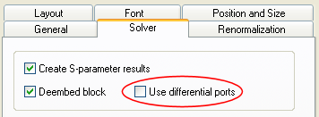
Next to the ’Deembed block’ check box is an additional box labeled ’Use differential ports’. Selecting it and pressing Apply will add the reference pins to the block as shown below.
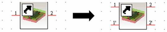
You can switch off this property again by removing the tick from the box and confirming the modification.
There are two different settings controlling the differential ports: ’Use differential cable ports’ applies for all ports of cable models created by CST CABLE STUDIO, and ’Use differential ports’ applies for all other ports. Both settings behave very similar. The only difference is the number of reference pins: For cable models, one reference pin per node is created (if the setting 'Connect to 3D' of the node is enabled), so all pins of this node share the same reference pin. For all other ports one reference pin per port is created. If the existing cable model does not support reference pins, the setting is greyed out in the dialog. This is the case for models created by CST CABLE STUDIO 2012 or earlier, or if no node is connected to a 3D shape. In the first case the setting will become available as soon as a new cable model is created witrh the current version of CST CABLE STUDIO.
Note
The ideal circuit ground is independent of ground planes that might exist in the 3D domain. It is simply a common reference for all circuit voltages. Both the single-pin and the dual-pin representation are valid for all ports of all blocks that offer this setting. Even the stripline model above may be simulated using the single-pin representation, since both differ only at the circuit side. The dual-pin representation is only needed if it is required by the connected circuit components.
The same train of thought concerns the ’Differential’ property of an external port. To this point, we have dealt with e.g. S-parameter simulations associated with ports referring to a common ground. Imagine a mixer simulation that considers a differential input. In this case, we need a reference pin for the external port, as well. To show it, select the ’Differential’ option inside the ’General’ frame of the External Port Properties - General page.

Press the Apply or the OK button to confirm the modification. The result is shown below where the reference pin is added at the end of the red line. The port itself can be connected as usual.

See also