![]()
![]()
|
Single Run: |
|
|
|
|
|
With Parameter Sweep: |

Introduction and Model Dimensions
In this tutorial you will analyze a sensor with the magnetostatics field simulator. The structure is a rotary encoder that consists of two iron yokes, a permanent magnet and two Hall sensors. Both yokes form a magnetic circuit that is driven by a cylindrical permanent magnet. Two Hall sensors are placed in the air gap between the yokes to measure the flux density. When the yokes are twisted, the B-field changes almost linearly with the rotation angle. After the construction process has been completed you will use the parameter sweep feature to check the linearity of the device.
We strongly suggest that you carefully read through the CST EM STUDIO Workflow & Solver Overview manual before starting this tutorial.

After launching the CST STUDIO SUITE you will enter the
start screen showing you a list of recently opened projects and allowing
you to specify the application which suits your requirements best. The
easiest way to get started is to configure a project template which sets
the basic settings that are meaningful for your typical application. Therefore
click on the Create Project ![]() button in the New Project
section.
button in the New Project
section.
Next you should chose the application area, which is Statics and Low Frequency for the example in this tutorial and then select the workflow by double-clicking on the corresponding entry.
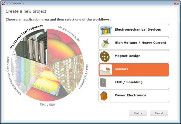
For the rotary encoder, please select Sensors
![]() Hall Sensors
Hall Sensors ![]() M-Static
M-Static
![]() .
.
At last you are requested to select the units which fit your application best. The rotary encoder in this tutorial has dimensions given in mm. Therefore select mm from the Dimensions drop-down list. For the specific application in this tutorial the other settings can be left unchanged. After clicking the Next button, you can give the project template a name and review a summary of your initial settings.
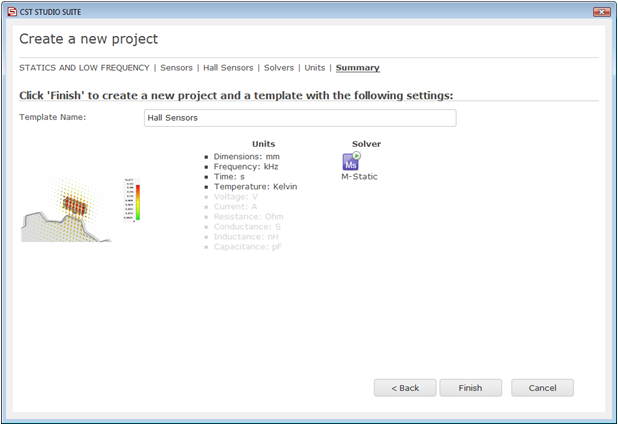
Finally, click the Finish button to save the project template and to create a new project with appropriate settings. CST EM STUDIO will be launched automatically due to the choice of the application area Statics and Low Frequency.
Please note: When you click again on File: New and Recent you will see that the recently defined template appears below the Project Templates section. For further projects in the same application area you can simply click on this template entry to launch CST EM STUDIO with useful basic settings. It is not necessary to define a new template each time. You are now able to start the software with reasonable initial settings quickly with just one click on the corresponding template.
Please note:
All settings made for a project template can be modified later on during
the construction of your model. For example, the units can be modified
in the units dialog box (Home:
Settings ![]() Units
Units ![]() ) and the solver type can be selected in the Home:
Simulation
) and the solver type can be selected in the Home:
Simulation ![]() Start Simulation drop-down list.
Start Simulation drop-down list.
Once you have entered the modeling view, the background
properties should be adjusted. Because the structure will be defined in
a vacuum background, you must define the size of the surrounding empty
space. Therefore, select Modeling:
Materials ![]() Background
Background ![]() to open the Background Properties
dialog box. The project template has already set the Material
type to Normal (i.e. Vacuum).
Furthermore, activate the checkbox Apply
in all directions and enter a Distance
value of 20. This value ensures an adequate distance between the calculation
domains boundaries and the structure. Confirm your settings by pressing
the OK button.
to open the Background Properties
dialog box. The project template has already set the Material
type to Normal (i.e. Vacuum).
Furthermore, activate the checkbox Apply
in all directions and enter a Distance
value of 20. This value ensures an adequate distance between the calculation
domains boundaries and the structure. Confirm your settings by pressing
the OK button.
Next set the working plane properties to make the drawing
plane large enough for your device. Because the structure has a maximum
extension of 40 mm along a coordinate direction, the working plane size
should be set to at least 40 mm. These settings can be changed in the
Working Plane Properties dialog
box (View:
Visibility ![]() Working Plane
Working Plane ![]() Working Plane Properties
Working Plane Properties
![]() ).
Set Size = 100, Width
= 1, Snap Width = 0.5 and deactivate
the Auto checkboxes. Leave the dialog box by pressing the OK
button.
).
Set Size = 100, Width
= 1, Snap Width = 0.5 and deactivate
the Auto checkboxes. Leave the dialog box by pressing the OK
button.
Now you can create the first cylinder. The easiest way
to do this is to activate the Cylinder
tool (Modeling:
Shapes ![]() Cylinder
Cylinder ![]() ). CST EM STUDIO now asks you for the center point
of the cylinder. You can double-click at the desired coordinates in the
drawing plane or use the Tab
key to enter the values numerically. Define the cylinder with
). CST EM STUDIO now asks you for the center point
of the cylinder. You can double-click at the desired coordinates in the
drawing plane or use the Tab
key to enter the values numerically. Define the cylinder with
Center point at X = 0, Y = 0,
Radius = 20, and
Height = 5.
The setting of the cylinders inner radius can be skipped by pressing the Esc key. The Cylinder dialog box will appear, displaying a summary of your previous input. You should now assign a meaningful Name to the cylinder, e.g. bottom yoke. Furthermore you need to define the iron material for the cylinder. Because no iron material has yet been defined, you should open the material definition dialog box by selecting [New Material...] from the Material drop-down list.
In this dialog box you should define a new Material name (e.g. Iron-1000) and set the Type to a Normal material. Afterwards, change the permeability Mue to 1000 and choose a color for the material by pressing the colored button. Finally confirm your settings by pressing the OK button.
|
|
|
Back in the cylinder creation dialog box you can also press the OK button to create the bottom yoke brick.

The next step is to model the yoke's shoulders. Therefore,
you should first move the drawing plane to the top of the bottom yoke.
This can be easily achieved by moving the local coordinate system. To
this end, click on Modeling:
WCS ![]() Align WCS
Align WCS ![]() (shortcut: w) and then double-click on the cylinder's
top face (maximum z-direction).
(shortcut: w) and then double-click on the cylinder's
top face (maximum z-direction).

Next rotate the working plane around the v-axis. Therefore,
select Modeling:
WCS ![]() Transform WCS
Transform WCS ![]() and click on the Rotate
control, and perform a rotation around the v-axis of -90 degrees.
and click on the Rotate
control, and perform a rotation around the v-axis of -90 degrees.
|
|
|
With an adjusted WCS it is fairly simple to create the
rotation body. Activate the Rotate Tool
by selecting Modeling:
Shapes ![]() Extrusions
Extrusions ![]() Rotate
Rotate ![]() .
.

You will be asked to enter the uv-coordinates of the profile to rotate. Again, you may enter them numerically or via the graphical user interface. As for the construction of the cylinder, use the Tab key to enter the following profiles coordinates:
|
Point |
U |
V |
|
1 |
0 |
-20 |
|
2 |
0 |
-15 |
|
3 |
5 |
-15 |
|
4 |
5 |
-20 |
|
5 |
0 |
-20 |
After the last point has been set, the Rotate Profile dialog box appears. Adjust the rotation angle: The Start Angle will be -30 degrees for a rotation Angle of 60 degrees around the U-Axis. The material should be Iron-1000. There is no need for a special name because the body will be added to the cylinder later; therefore, just press OK to define the solid.
|
|
|
The yoke's second shoulder can be created by a mirror
transformation. Select the previously created shoulder by double-clicking
on it. Then open the Transform
dialog box via the context menu of by selecting Modeling: Tools![]() Transform
Transform![]() Mirror
Mirror
![]() . In this dialog box select the Operation
to Mirror before you set the
V-coordinate of the Mirror
plane normal to 1. Switch on the Copy
and Unite options to copy the
existing shape before mirroring it, and to unite the original shape with
the mirrored copy.
. In this dialog box select the Operation
to Mirror before you set the
V-coordinate of the Mirror
plane normal to 1. Switch on the Copy
and Unite options to copy the
existing shape before mirroring it, and to unite the original shape with
the mirrored copy.
|
|
|
Finally press OK
to create the second shoulder. In order to unite the bottom cylinder with
the shoulders, select the cylinder with a double-click or in the navigation
tree and activate the Boolean Add
tool by selecting Modeling:
Tools ![]() Boolean
Boolean ![]() . Now you will be prompted to select the object to be added.
Double-click on one of the shoulders and confirm with the Return
key. The construction of the bottom yoke is now finished.
. Now you will be prompted to select the object to be added.
Double-click on one of the shoulders and confirm with the Return
key. The construction of the bottom yoke is now finished.
The construction of the permanent magnet consists of two steps. First, you must create a cylinder with a new material and then assign the permanent magnet properties to the object.
For the cylinder definition the WCS has to be rotated
back. Simply press Shift-v to
rotate the WCS 90 degrees around the v axis counter-clockwise to its previous
orientation. Now activate the cylinder tool again (Modeling:
Shapes![]() Cylinder
Cylinder
![]() )
and use the Tab key to define
a cylinder with
)
and use the Tab key to define
a cylinder with
Center point: u = 0, v = 0.
Radius: 10.
Height: 11.
Press the Esc key to skip the definition of the inner radius. In the Cylinder dialog box, select a Name for the shape (e.g. magnet). Before you create the shape you should define a new material where the material properties will be stored. The procedure is the same as for the yoke's material:
Select the [New Material...] item in the Material drop-down list.
Enter a Material name (e.g. magnet material).
Set the Type to Normal.
Select a color.
Confirm with OK.
Back in the cylinder dialog box, check your settings and create the cylinder by pressing OK.
|
|
|
The next step is to define the permanent magnet's magnetization
vector. Therefore, activate the permanent magnet tool by selecting Simulation:
Source and Loads
![]() Permanent Magnet
Permanent Magnet
![]() .
Now you will be asked to select the volume surface for the magnet. Move
the mouse cursor on the previously defined magnet cylinder and select
it with a double-click. The selected surface will be highlighted in red
and a dialog box will open where you should define the magnet's properties:
.
Now you will be asked to select the volume surface for the magnet. Move
the mouse cursor on the previously defined magnet cylinder and select
it with a double-click. The selected surface will be highlighted in red
and a dialog box will open where you should define the magnet's properties:
|
|
|
Enter 0.2 for the W-component of the Remanent magnetization vector. Pressing the Preview button displays the orientation of the current magnetization vector. The approximate value of relative permeability 1 is correct in this case and can be left unchanged. To store your settings press OK. The permanent magnet definition can always be reviewed by selecting its icon in the Permanent Magnets folder in the navigation tree.
It is not necessary to model the Hall sensors because the material properties of the sensors are neutral for a magnetostatic simulation. Nevertheless, the sensors are included for two reasons: to visualize their positions and to refine the mesh within the sensor regions.
Before the sensors are constructed, the WCS must be shifted
along the w-axis. Enter the Transform
Local Coordinates dialog box by selecting Simulation:
WCS ![]() Transform WCS
Transform WCS ![]() , enter DW = 5
for a shift along the w-axis and confirm with OK.
The working plane has been shifted to the top faces of the shoulders,
where the Hall sensors will be constructed.
, enter DW = 5
for a shift along the w-axis and confirm with OK.
The working plane has been shifted to the top faces of the shoulders,
where the Hall sensors will be constructed.
With the WCS in the proper location, the construction
of the first Hall sensor is fairly simple. Enter the cylinder tool again
(Modeling:
Shapes ![]() Cylinder
Cylinder ![]() ) and define a cylinder with
) and define a cylinder with
Center point: U = 0 and V = 17.5
Radius: 2
Height: 1
Just as for the creation of the permanent magnet, you can enter a meaningful name (e.g. hall sensor 1). You should also define a new material with normal properties (Eps = 1 and Mue = 1) for the sensors. Do not forget to select a unique color to improve the visualization. Confirm your settings with OK.
|
|
|
The second Hall sensor will be created by a transformation
of the first one. Select the Hall sensor by double-clicking on it and
activate the Transform dialog
box (Modeling: Tools
![]() Transform
Transform
![]() ). Here, you should select the Operation
type Translate and set the Translation vector's V-component
to a value of -35. To create a transformed copy of the first sensor,
activate the Copy box. Press
the Preview button to check your
settings before you confirm with OK.
). Here, you should select the Operation
type Translate and set the Translation vector's V-component
to a value of -35. To create a transformed copy of the first sensor,
activate the Copy box. Press
the Preview button to check your
settings before you confirm with OK.
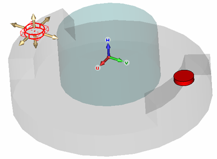
Finally, select the newly created item in the navigation, press F2 and rename it, e.g. to hall sensor 2.
The last steps include the construction of the top yoke
and the rotation of the bottom yoke to the sensors' zero position. First,
the bottom yoke will be rotated to its final position. Therefore, select
the bottom yoke with a double-click (or its item in the navigation tree)
and open the Transform dialog
box (Modeling: Tools
![]() Transform
Transform
![]() ). Select the Rotate
Operation and enter a Rotation angle
of 20 degrees around the W-axis.
After a Preview, finalize with
the OK button.
). Select the Rotate
Operation and enter a Rotation angle
of 20 degrees around the W-axis.
After a Preview, finalize with
the OK button.
|
|
|
To create the top yoke, re-select the bottom yoke and
enter the Transform dialog box
again (Modeling: Tools
![]() Transform
Transform
![]() ).
).
Select the Mirror Operation.
Enter the value W0 = 0.5 to shift the Mirror plane origin along the w-axis.
Enter W = 1 to define the uv-plane as the mirror plane.
Select Copy to create a transformed copy of the bottom yoke.
Use the Preview button to check and confirmed with OK.
|
|
|
Finally, the newly created solid should be renamed. Select
its item in the navigation tree (Components
![]() component1
component1 ![]() bottom yoke_1) and press F2
(or choose Rename from the context
menu). The item text of the selected body can be edited now. Enter an
appropriate name (e.g. top yoke) and confirm with the Return key.
bottom yoke_1) and press F2
(or choose Rename from the context
menu). The item text of the selected body can be edited now. Enter an
appropriate name (e.g. top yoke) and confirm with the Return key.
The geometric construction is now complete. Before the simulation can be started, some physical settings must be adjusted.
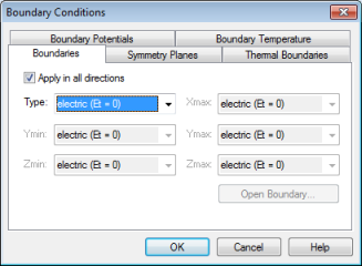
The calculation domain is covered and terminated by six faces. You must assign a boundary condition to each of these faces. Because the structure is almost in a closed magnetic circuit, it is sufficient to use boundaries of type electric. The electric boundary condition forces the normal component of the magnetic flux density to be zero. It appears to be like a perfect electric conductor (PEC).
Because fields outside the magnetic circuit do not have
significant impact on the devices behavior, it is advisable to add some
space around the structure and use electric boundaries. The space was
added already at the beginning of this tutorial. You just need to define
the electric boundary conditions by entering the Boundary
Conditions dialog box (Simulation:
Settings ![]() Boundaries
Boundaries
![]() )
and choosing the type electric (Et=0)
for all directions. In addition to the dialog box entries, the boundary
conditions are also displayed in the main view. Finally confirm your settings
with the OK button.
)
and choosing the type electric (Et=0)
for all directions. In addition to the dialog box entries, the boundary
conditions are also displayed in the main view. Finally confirm your settings
with the OK button.
For the numerical solution of a field problem, it is necessary to discretize its calculation domain. This means that the volume will be subdivided into small cells, or in alternate terms that a mesh will be put on the structure. CST EM STUDIO is capable of generating a calculation mesh automatically which can be modified by the user in many ways. The second chapter of this tutorial will focus on the hexahedral solver method, while the third one introduces the tetrahedral method.
To examine the automatically generated mesh, first switch
the mesh type to Hexahedral via
Simulation:
Mesh ![]() Global Properties
Global Properties ![]() Hexahedral
Hexahedral ![]() . You will enter the Mesh
Properties dialog box automatically. The project template has set
the Lower mesh limit to 20 and
the Mesh line ratio limit to
50. Confirm with OK and activate
the Mesh view (Simulation:
Mesh
. You will enter the Mesh
Properties dialog box automatically. The project template has set
the Lower mesh limit to 20 and
the Mesh line ratio limit to
50. Confirm with OK and activate
the Mesh view (Simulation:
Mesh ![]() Mesh View
Mesh View ![]() ).
).

The above picture shows the x-meshing plane at the x-position
= 0. You can use the tools in the Mesh:
Mesh Plane group to switch to
another mesh plane normal (![]() ,
, ![]() ,
, ![]() - shortcuts x, y, z) or to vary the mesh
plane index (
- shortcuts x, y, z) or to vary the mesh
plane index (![]() ,
, ![]() - or up/down cursors).
- or up/down cursors).
This mesh is too coarse inside the air gap and the iron yokes to deliver reliable results. The strongest refinement needs to be applied to the Hall sensors and the air-gaps between the yokes shoulders, because the highest energy values are expected within these regions. Moreover, the magnetic fluxes will change rapidly at the material transitions at the air-gaps. The two yokes have to be refined with a lower factor because no high energy values or rapid field variations are expected inside these regions.
In order to refine the mesh in the air-gaps you will assign solid-based mesh properties to the two hall sensors. Select hall sensor 1 and open the corresponding Local Mesh Properties dialog box via the context menu. For this example, a volume refinement is necessary. Therefore, activate the Use local volume refinement factor and set the factor to 8. In order to extend the refined mesh area to the complete air gap, enter the values 10 mm, 5 mm and 1 mm for the X / Y / Z extension ranges. Finally press OK.
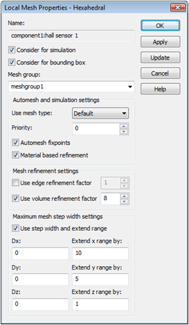
A new folder will appear in the navigation tree: Groups ![]() Mesh Groups
Mesh Groups ![]() meshgroup1 corresponding to the recently
defined local refinement settings for the first hall sensor. To apply
the same local mesh property settings also to the second sensor hall sensor 2 you simply drag and drop
its item Components
meshgroup1 corresponding to the recently
defined local refinement settings for the first hall sensor. To apply
the same local mesh property settings also to the second sensor hall sensor 2 you simply drag and drop
its item Components ![]() component1
component1 ![]() hall sensor 2 in the navigation tree
to this mesh group (Groups
hall sensor 2 in the navigation tree
to this mesh group (Groups ![]() Mesh Groups
Mesh Groups ![]() meshgroup1).
meshgroup1).
Please note:
A high refinement setting for a certain solid is only recognized when
the global Mesh line ratio limit
value that describes the ratio between the smallest and the largest line
distance, is not exceeded. This value can be verified by opening the global
Mesh Properties dialog box (Simulation:
Mesh ![]() Global
Properties
Global
Properties
![]() ). The Mesh
line ratio limit value, that has been set initially by the project
template to 50, is relatively high. Consequently, a volume refinement
factor for a single solid is considered correctly.
). The Mesh
line ratio limit value, that has been set initially by the project
template to 50, is relatively high. Consequently, a volume refinement
factor for a single solid is considered correctly.
Now you might want to take a look at the refined mesh around the Hall sensors:

The mesh inside the air-gaps has been refined adequately, but the yokes need further refinement to sample the magnetic flux density properly. Apply the refinement procedure from the hall sensors for the two iron yokes:
Select the bottom yoke.
Select Local Mesh Properties from the context menu.
Set a local volume refinement factor of 3.
Set the X, Y, Z extension ranges to a value of 2 and confirm with OK.
Drag
the top yoke item in the navigation
tree to the newly created mesh group (meshgroup2).
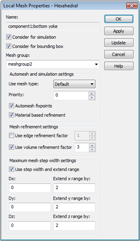
Finally, the mesh view at the x-meshing plane at the x=0 position should resemble the following screenshot:

Now the fields are
sufficiently sampled inside the most important regions. Before starting
the solver process, leave the Mesh View
by selecting Mesh: Close ![]() Close
Mesh View
Close
Mesh View ![]() .
.
The solver parameters
are specified in the magnetostatic solver control dialog box that can
be opened by selecting Simulation: Solver
![]() Start
Simulation
Start
Simulation ![]() . Make sure that the Hexahedral
Mesh is selected from the Mesh
type list and that the Adaptive
mesh refinement is not checked. Finally, start the simulation process
by pressing the Start button.
. Make sure that the Hexahedral
Mesh is selected from the Mesh
type list and that the Adaptive
mesh refinement is not checked. Finally, start the simulation process
by pressing the Start button.
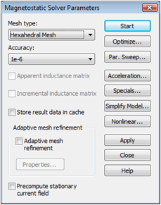
Congratulations, you have simulated the rotary encoder! Let's examine the calculated fields. You will notice that some new entries have appeared in the Navigation Tree:

Please note that the results might differ slightly depending on the operating system and the architecture of the machine with which they were computed.
Because this tutorial focuses on the magnetic flux density
within the Hall sensors, the subject of interest is the B-Field
item in the tree. Select 2D/3D Results
![]() B-Field to visualize the magnetic flux density in the entire calculation
domain:
B-Field to visualize the magnetic flux density in the entire calculation
domain:
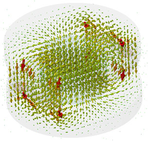
For a better view of the field distribution it is sometimes
advisable to modify the Object's
scaling and density in the Plot Properties
(2D/3D Plot: Plot
Properties ![]() Properties
Properties ![]() ). This plot gives you an initial impression
about the fields in and around the magnetic circuit. For a more detailed
analysis it is appropriate to activate the 2D plot in a plane, by selecting
2D/3D Plot:
Sectional
View
). This plot gives you an initial impression
about the fields in and around the magnetic circuit. For a more detailed
analysis it is appropriate to activate the 2D plot in a plane, by selecting
2D/3D Plot:
Sectional
View ![]() 3D
Fields on 2D Plane
3D
Fields on 2D Plane ![]() .
.
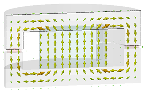
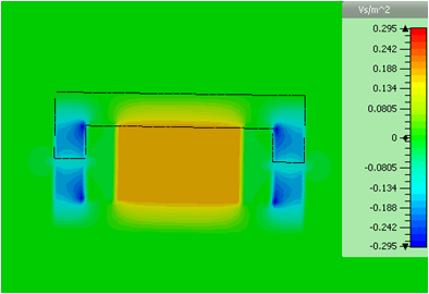
Again, you can alter the number and the size of arrows
in the Plot Properties dialog
(Arrows/Scaling). When you select
a component in the B-Field folder
(e.g. 2D/3D Results![]() B-Field
B-Field![]() Z), a contour plot of the selected
component appears. Please note, that for general purposes, the color ramp
(which is usually positioned at the right hand side of the main view)
is scaled by default to the overall 3D maximum of the selected result.
You can easily scale it to an optimal view of the selected field via the
entry Autoscale in the context
menu of the main view .
Z), a contour plot of the selected
component appears. Please note, that for general purposes, the color ramp
(which is usually positioned at the right hand side of the main view)
is scaled by default to the overall 3D maximum of the selected result.
You can easily scale it to an optimal view of the selected field via the
entry Autoscale in the context
menu of the main view .
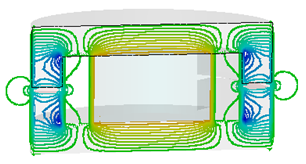
It is also possible to modify plot settings, therefore
select 2D/3D Plot: Plot
Properties ![]() Properties
Properties ![]() and change the Plot
type to Isoline.
and change the Plot
type to Isoline.
For more information on this subject, please refer to the online help (Help button or F1 key).
This chapter introduces the tetrahedral solver method for the magnetostatics solver. A comparison between the two available methods allows you to verify the accuracy of the results. Although the hexahedral meshing method will be faster for this particular example, a tetrahedral mesh is usually the first choice when thin and curved structure details have to be sampled accurately. The seamless combination of these different techniques in a homogeneous environment is another outstanding feature of CST EM STUDIO.
First switch to the tetrahedral meshing type via Home:
Mesh ![]() Global
Properties
Global
Properties ![]() Tetrahedral
Tetrahedral
![]() . The global Mesh
Properties dialog box will open automatically. As the tetrahedral
solver uses second order elements by default (meaning high accuracy results
at the cost of increased memory requirements), the basic sampling rate
obtained with the Min. number of steps
value of 10 is sufficient for this example. Thus, set this value to 10
and leave the dialog box by pressing OK.
The mesh is not generated automatically, but a message appears inside
the main view after activating the Mesh
view (Home:
Mesh
. The global Mesh
Properties dialog box will open automatically. As the tetrahedral
solver uses second order elements by default (meaning high accuracy results
at the cost of increased memory requirements), the basic sampling rate
obtained with the Min. number of steps
value of 10 is sufficient for this example. Thus, set this value to 10
and leave the dialog box by pressing OK.
The mesh is not generated automatically, but a message appears inside
the main view after activating the Mesh
view (Home:
Mesh ![]() Mesh
View
Mesh
View ![]() ) informing you how to enforce the mesh creation.
) informing you how to enforce the mesh creation.
In contrast to the hexahedral mesh generation, tetrahedral
meshes require substantially more time to be created. As a consequence,
this operation is only performed upon request. To create a first
tetrahedral mesh simply click on Mesh:
Mesh Control ![]() Update
Update
![]() .
.
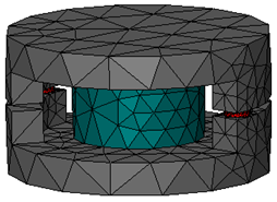
To check the mesh on a 2D cut-plane, activate the cutting
plane by pressing Shift+C or
by selecting View:
Sectional View ![]() Cutting
Plane
Cutting
Plane ![]() :
:
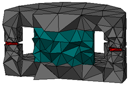
Use the Up/Down arrow keys to
get an impression of the mesh inside the structure. Alternatively, you
can adjust the cutting plane settings in the Cutting
Plane Properties dialog box (View:
Sectional
View ![]() Cutting
Plane
Cutting
Plane ![]() Properties
Properties ![]() ) by moving the Position
slider and switching the Axis
radio-buttons. Leave the dialog box by pressing the Close
button.
) by moving the Position
slider and switching the Axis
radio-buttons. Leave the dialog box by pressing the Close
button.
You might also want to examine the mesh inside the background
regions. To activate the background material display, select View:
Options ![]() View
Options
View
Options ![]() (Alt+v) and activate
the Background material checkbox
on the General tab. To update
the view, finally press Preview.
If the cutting plane is still activated you should get a picture similar
to the following:
(Alt+v) and activate
the Background material checkbox
on the General tab. To update
the view, finally press Preview.
If the cutting plane is still activated you should get a picture similar
to the following:
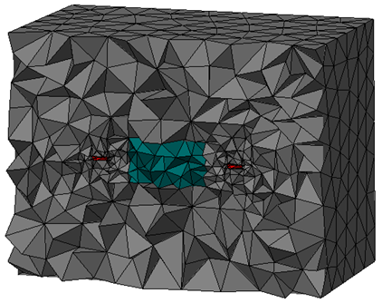
To restore the 3D mesh view, switch off the cutting plane
by selecting View:
Sectional
View ![]() Cutting
Plane
Cutting
Plane ![]() again. Afterwards, reenter the View Options dialog box to disable
the Background material display.
again. Afterwards, reenter the View Options dialog box to disable
the Background material display.
In the same manner that you improved the mesh for the hexahedral mesh by defining refinements for particular solids, you should do the same for the tetrahedral mesh. Therefore, select the first hall sensor (with the mesh view activated) and open the context sensitive menu with a right-mouse-click. Select Local Mesh Properties from the context menu in order to open the corresponding dialog box.
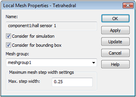
For tetrahedral meshes a Maximum step width can be specified. Enter a value of 0.25 and leave the dialog box by pressing OK. If requested, confirm the deletion of the current results/mesh. As the second hall sensor belongs to the same mesh group, it will inherit the mesh properties of the first one automatically, which is fine for our purposes. To refine the yokes and magnet, apply the same procedure to these solids. Instead of using a Maximum step width of 0.25, use a step width of 3.
After a final update (Mesh:
Mesh Control
![]() Update
Update ![]() ) that may take a couple of seconds,
you should see a mesh similar to the following one:
) that may take a couple of seconds,
you should see a mesh similar to the following one:
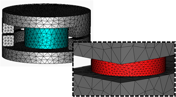
Open the magnetostatic solver control dialog box by selecting
Simulation:
Solver ![]() Start
Simulation
Start
Simulation ![]() . The Mesh type
is already set to Tetrahedral Mesh.
Without any further modifications you can start the simulation process
by pressing the Start button.
Again you can observe the solver process in the Progress and Message windows
in the lower part of the main view.
. The Mesh type
is already set to Tetrahedral Mesh.
Without any further modifications you can start the simulation process
by pressing the Start button.
Again you can observe the solver process in the Progress and Message windows
in the lower part of the main view.
Congratulations, you have simulated the rotary encoder with the tetrahedral meshing method. As for the hexahedral simulation workflow, you are invited to examine the result fields. A first look at the Navigation Tree shows that entries for the Magnetostatic fields and flux densities have been added.

Again, you can quickly examine the B-Field by clicking on its icon in the navigation tree:
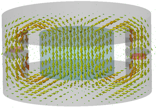
To observe the fields in a 2D cut plane select 2D/3D Plot:
Sectional View ![]() 3D
Fields on 2D Plane
3D
Fields on 2D Plane ![]() from the Plot
ribbon or from the context menu:
from the Plot
ribbon or from the context menu:
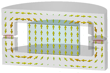
To change plot positions and other settings, select 2D/3D Plot: Plot
Properties ![]() Properties
Properties ![]() . The tetrahedral mesh method is often
applied on structures that cannot be sampled adequately inside a structured
Cartesian mesh without reasonable effort. Sometimes you may prefer observing
the fields in an arbitrary 2D cutplane because the interesting parts of
a structure are not aligned to the x/y/z Axis. Therefore, select the Free cutplane control and use the three
location sliders to navigate the 2D cutplane inside the structure:
. The tetrahedral mesh method is often
applied on structures that cannot be sampled adequately inside a structured
Cartesian mesh without reasonable effort. Sometimes you may prefer observing
the fields in an arbitrary 2D cutplane because the interesting parts of
a structure are not aligned to the x/y/z Axis. Therefore, select the Free cutplane control and use the three
location sliders to navigate the 2D cutplane inside the structure:
|
|
|
Before you continue with the parameterization of the structure, leave the field view, e.g. by selecting the Components folder in the navigation tree. In case the cutting plane is still active, switch it off (Shift+C).
One of the most powerful features of CST EM STUDIO is the parameterization ability. This means that you can define variables and use them, for instance, for the definition of a solid or excitation. The solver contains the option to vary parameters within a user-defined range. One-dimensional results will be summarized in tables and can be plotted as a function of the varied parameters.
Because this tutorial deals with a rotary encoder, the
angle of rotation between the top and the bottom yoke will be parameterized.
Therefore, select the top yoke and enter the transformation dialog box
(Modeling:
Tools ![]() Transform
Transform ![]() ). Select the Operation
Rotate and enter the parameter's
name (e.g. angle) with a minus
sign into the W field of the
Rotation angles frame. To rotate
the top yoke around the Shape center
activate the corresponding checkbox as well:
). Select the Operation
Rotate and enter the parameter's
name (e.g. angle) with a minus
sign into the W field of the
Rotation angles frame. To rotate
the top yoke around the Shape center
activate the corresponding checkbox as well:
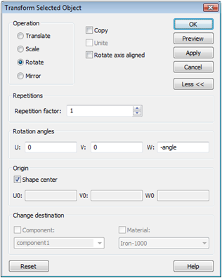
Check your settings with the Preview button. The next dialog box opens and prompts you to enter a valid value for the new variable. Set its value to 10 and enter a helpful description text before confirming with OK. Leave the transformation dialog box as well with OK and confirm the deletion of the results if required. The recently defined parameter appears inside the Parameter List window which is usually docked at the lower left part of the user interface:
|
|
|
We will first start
the Parameter Sweep using the
hexahedral grid and then compare the results with those obtained with
the tetrahedral mesh. Thus, enter the magnetostatic solver dialog box
(Simulation: Solver ![]() Start Simulation
Start Simulation
![]() ),
and switch the Mesh type back
to the Hexahedral mesh. Then
press the Par. Sweep button to
open the Parameter Sweep dialog
box.
),
and switch the Mesh type back
to the Hexahedral mesh. Then
press the Par. Sweep button to
open the Parameter Sweep dialog
box.
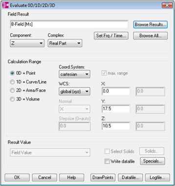
To add a new watch, click on the Result Template button. The Template Based Postprocessing dialog box appears where you should select the template group 2D and 3D Field Results and the postprocessing step Evaluate Field in arbitrary Coordinates. Another dialog box will open requiring the type of the field, its component and the position to be watched. For our purposes, enter B-Field [Ms] in the Field Result edit field. The Z-component of the B-field shall be monitored at the position X = 0, Y = 17.5, Z = 10.5. Thus, select 0D = Point in the Calculation Range frame and enter the appropriate coordinates in the corresponding edit fields for X, Y and Z. Finally, select the Z-component in the Component drop-down list.
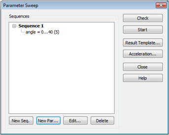
Confirm the settings with OK, and leave the Template Based Postprocessing dialog box with the Close button. The next step is to define a new parameter sequence. After pressing the New Seq. button, you can add a new parameter to this sequence by clicking the New Par. button. A new dialog box appears and you can select the previously defined parameter Name (angle) from a list. Check the Sweep box and enter a range From 0 To 40 with 5 Samples. After confirming with OK, the Parameter Sweep dialog box should appear as follows:
Now the calculation
sequence can be started with the Start button. After the sweep has finished,
leave the Parameter Sweep dialog
box with the Close button. Finally,
you can examine the result of the parameter sweep by selecting Tables
![]() 0D Results
0D Results ![]() B-Field (Ms)_Z_0D in the navigation tree.
B-Field (Ms)_Z_0D in the navigation tree.
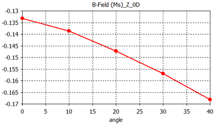
The diagram shows the variation of the B-field inside the Hall sensor versus the rotation angle of the sensor.
Before restarting the parameter sweep with the tetrahedral mesh method, it is advisable to copy the previously created result curve to a new folder, to allow for an easy comparison between the two methods.
First, select the
1D Results folder in the navigation
tree, then create a new tree folder by selecting New
Tree Folder from the context menu. Enter an appropriate name (e.g.
Compare) and press Enter. To
copy the parameter sweep result curve (Tables
![]() 0D Results
0D Results ![]() B-Field (Ms)_Z_0D), select Copy
from its context menu and then click again on the previously created folder
1D Results
B-Field (Ms)_Z_0D), select Copy
from its context menu and then click again on the previously created folder
1D Results ![]() Compare where you should select Paste from the context menu. Finally
rename the newly created item. A meaningful and short name is simply HEX.
Compare where you should select Paste from the context menu. Finally
rename the newly created item. A meaningful and short name is simply HEX.

After saving the
hexahedral result curve you can continue to start the tetrahedral parameter
sweep. Enter the magnetostatic solver dialog box (Simulation: Solver ![]() Start Simulation
Start Simulation
![]() )
and switch to the tetrahedral meshing type. Again, press the Par.
Sweep... button. At this point old results will be deleted, when
present. Confirm the deletion of the results. You already saved the 1D
curve from the last parameter sweep to a non-deletable folder. Without
any further changes you should start the parameter sweep again. After
all calculations have been completed, you can close the Parameter Sweep
dialog box with the Close button.
)
and switch to the tetrahedral meshing type. Again, press the Par.
Sweep... button. At this point old results will be deleted, when
present. Confirm the deletion of the results. You already saved the 1D
curve from the last parameter sweep to a non-deletable folder. Without
any further changes you should start the parameter sweep again. After
all calculations have been completed, you can close the Parameter Sweep
dialog box with the Close button.
To compare the new result curve with the old one, perform the following steps:
Select
the curve to be copied in the navigation tree (Tables
![]() 0D Results
0D Results ![]() B-Field (Ms)_Z_0D).
B-Field (Ms)_Z_0D).
Copy this curve to the clipboard via the context menu (or press Ctrl+C).
Select
the 1D Results ![]() Compare folder.
Compare folder.
Paste the curve to be copied via the context menu (or press Ctrl+V).
Rename the new curve (F2) e.g. to TET.
If you select the folder Compare with the copied curves, both will be plotted in one diagram:
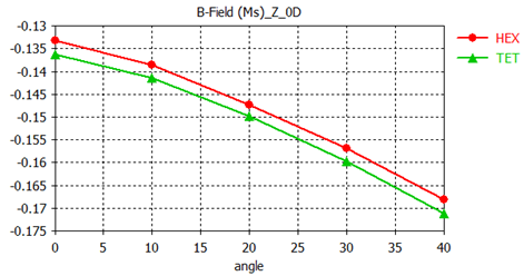
Apparently, a small gap is present between the curves (approximately 2% difference). This difference results from the meshing methods producing different errors and therefore different results. This difference reduces significantly when the meshes for both methods are refined. In addition to the mesh adaptation feature (which is discussed in detail in the CST EM STUDIO Workflow & Solver Overview manual and shortly explained in the next section), the availability of two different meshing methods offers a powerful alternative to validate simulation results.
A static field calculation is mainly affected by two sources of numerical inaccuracies:
Numerical errors introduced by the iterative linear equation system solver.
Inaccuracies arising from the finite mesh resolution.
In this section we provide some hints how to minimize these errors and achieve highly accurate results.
CST EM STUDIO uses an iterative linear equation system solver to solve the discretized field problem. This means that the iterative solver will stop a calculation if a given accuracy has been reached. In general, the accuracy setting of 1e-6 is sufficient for most calculations. However, in some cases the solver will give you a warning that the results are inaccurate and that you should consider increasing the solver accuracy.
Inaccuracies arising from the finite mesh resolution are usually more difficult to estimate. The only way to ensure the accuracy of the solution is to increase the mesh resolution and to recalculate the results. When they no longer change significantly when the mesh density is increased, then convergence has been achieved.
In the example above, a modified default mesh has been
used. The easiest way to test the accuracy of the results is to use the
fully automatic mesh adaptation that can be switched on by checking the
Adaptive mesh refinement option
in the solver control dialog box (Simulation: Solver ![]() Start Simulation
Start Simulation
![]() ).
When you start the solver again, please keep in mind that the calculation
is performed for only one parameter setting (angle
= 10). After the mesh adaptation procedure has finished, you can
visualize the energy deviation for two subsequent passes by selecting
1D Results
).
When you start the solver again, please keep in mind that the calculation
is performed for only one parameter setting (angle
= 10). After the mesh adaptation procedure has finished, you can
visualize the energy deviation for two subsequent passes by selecting
1D Results ![]() Adaptive Meshing
Adaptive Meshing ![]() Error from the navigation tree:
Error from the navigation tree:
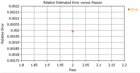
As evident in the above plot, the maximum energy deviation
is below 1% between the first and the second pass, indicating that the
accuracy of the first calculation was already sufficient. If you view
the energy curve (1D Results ![]() Adaptive Meshing
Adaptive Meshing ![]() Energy), you can watch the energy values vary
from pass to pass.
Energy), you can watch the energy values vary
from pass to pass.
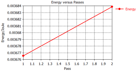
The deviation between the first and the second run is below 1%. In many cases, global results like energies are less susceptible to discretization errors than local results such as field values at certain positions.
Congratulations! You have just completed the Magnetostatic sensor tutorial that should have provided you with a good working knowledge on how to use the magnetostatic solver. The following topics have been covered:
General modeling considerations, using templates, etc.
Model a cylindrical structure by using the cylinder-, rotation- and transformation tools.
Define a permanent magnet.
Define boundary conditions.
Apply changes to the automatically generated mesh.
Start the magnetostatic solver.
Visualize the magnetic fields.
Run the Magnetostatic solver with the tetrahedral meshing method.
Perform a parameter sweep with hexahedral and tetrahedral meshes.
Obtain accurate and converged results using the automatic mesh adaptation.
You can obtain more information on each particular step from the online help system that can be activated either by pressing the Help button in each dialog box or by pressing the F1 key at any time to obtain context sensitive information.
In some instances, we have referred to the CST EM STUDIO Workflow & Solver Overview manual that is also a good source of information for general topics. In addition to this tutorial, you can find additional magnetostatic calculation examples in the Examples folder in your installation directory. Each of these examples contains a Readme item in the navigation tree that will give you some more information about the particular device.
And last but not least: Please also visit one of the training classes, held regularly at a location near you. Thank you for using CST EM STUDIO.