![]()
![]()

Geometric Constructions and Solver Settings
This tutorial deals with the simulation of a simple electrometer device that can be used for voltage measurements. The model used for the electrometer consists of three parts: the electrometer's scale, the ground and the pointer. The main dimensions of the electrometer device are shown in Figure 1.

Figure 1: The Model and its main dimensions
The results of interest are the capacitance and the torque for different angles of the pointer. A parameter sweep with a user-defined watch will be used for the simulation of the electrometer device. Finally, the results will be discussed.
We strongly suggest that you carefully read through the CST EM STUDIO Workflow & Solver Overview manual before starting this tutorial.
This tutorial demonstrates how to perform a capacitance calculation. It will guide you through the construction of a simple electrometer for voltage measurements. For details concerning geometrical constructions please refer also to the online help and the CST EM STUDIO Workflow & Solver Overview manual. Please note that the project file with the complete geometry is delivered with the installation and accessible from the Examples Overview (or the button Run Example at the beginning of this page).
After launching the CST STUDIO SUITE you will enter the
start screen showing you a list of recently opened projects and allowing
you to specify the application which suits your requirements best. The
easiest way to get started is to configure a project template which sets
the basic settings that are meaningful for your typical application. Therefore
click on the Create Project ![]() button in the New Project
section.
button in the New Project
section.
Next you should chose the application area, which is Statics and Low Frequency for the example in this tutorial and then select the workflow by double-clicking on the corresponding entry.

For the electrometer device, please select Sensors
![]() Capacitive Sensors
Capacitive Sensors ![]() E-Static
E-Static
![]() .
.
At last you are requested to select the units which fit your application best. In this tutorial all geometrical dimensions in this example are given in cm. Therefore select cm from the Dimensions drop-down list. For the specific application in this tutorial the other settings can be left unchanged. After clicking the Next button, you can give the project template a name and review a summary of your initial settings.
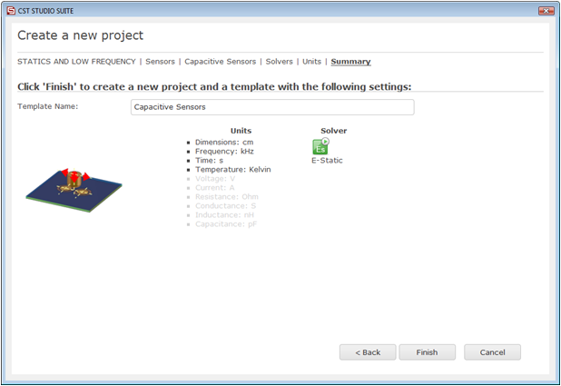
Finally, click the Finish button to save the project template and to create a new project with appropriate settings. CST EM STUDIO will be launched automatically due to the choice of the application area Statics and Low Frequency.
Please note: When you click again on File: New and Recent you will see that the recently defined template appears below the Project Templates section. For further projects in the same application area you can simply click on this template entry to launch CST EM STUDIO with useful basic settings. It is not necessary to define a new template each time. You are now able to start the software with reasonable initial settings quickly with just one click on the corresponding template.
Please note:
All settings made for a project template can be modified later on during
the construction of your model. For example, the units can be modified
in the units dialog box (Home:
Settings ![]() Units
Units ![]() ) and the solver type can be selected in the Home:
Simulation
) and the solver type can be selected in the Home:
Simulation ![]() Start Simulation drop-down list.
Start Simulation drop-down list.
The construction steps of the electrometers scale are based on the creation of two circles, extrusion of a planar curve to build a solid and blending the edges of the solid.
To create the first circle, select Modeling: Curves
![]() Curves
Curves ![]() Circle
Circle ![]() .
Now the circle creation mode is active allowing you to enter the circles
coordinates either by using the mouse or by keyboard input. When you press
the Shift+Tab keys simultaneously,
you can enter first the center point and then the radius numerically.
Alternatively you can directly enter the Circle
dialog box by pressing Esc. For
this example, create a circle with
.
Now the circle creation mode is active allowing you to enter the circles
coordinates either by using the mouse or by keyboard input. When you press
the Shift+Tab keys simultaneously,
you can enter first the center point and then the radius numerically.
Alternatively you can directly enter the Circle
dialog box by pressing Esc. For
this example, create a circle with
Center at X=0 and Y=0 and
Radius 3.0.
The preview of the circle is displayed in the Modeler
View with orange color according to the settings in the dialog box. After
all settings are confirmed with OK,
the circle color changes to blue and a new entry appears in the Navigation Tree under Curves
![]() curve1
curve1 ![]() circle 1.
circle 1.
To construct the second circle, select again Modeling:
Curves ![]() Curves
Curves ![]() Circle
Circle ![]() .
Create a circle with
.
Create a circle with
Center at X = 2 and Y = 0 and
Radius 3.6.
The two circles intersect. They are used for the next construction step to define an outline of a sickle-like structure. Therefore, one segment of each circle has to be deleted as shown below.

You can delete the two marked
circle segments by trimming the two circles and selecting the circle segments
you want to delete. Please select circle1 by either double-clicking on
the initially created circle in the Modeler View or by selecting Curves ![]() curve1
curve1 ![]() circle1 in the Navigation
Tree.
circle1 in the Navigation
Tree.
To start the trim action,
select Modeling:
Curves ![]() Curve Tools
Curve Tools ![]() Trim Curves
Trim Curves ![]() from the menu bar or use the shortcut #. Then select circle2
and confirm with the Return key.
Now the interactive trim tool highlights all curve parts that can be deleted.
Delete the curve segments shown in the previous screenshot by double-clicking
on the appropriate circle segment. Please check
the model against the screenshot below. To confirm the trim action, press
Return.
from the menu bar or use the shortcut #. Then select circle2
and confirm with the Return key.
Now the interactive trim tool highlights all curve parts that can be deleted.
Delete the curve segments shown in the previous screenshot by double-clicking
on the appropriate circle segment. Please check
the model against the screenshot below. To confirm the trim action, press
Return.

In the next construction
step, the sickle-like outline is used to create a solid. Therefore,
the curve defining the sickle-like outline is extruded. First, please
select Modeling:
Curves ![]() Curve Tools
Curve Tools ![]() Extrude
Curve
Extrude
Curve ![]() .
To define the profile for the extrusion double-click on the inner curve
item of the circle segment of the last created circle (circle2).
The Extrude Planar Curve dialog box opens, enabling you to set the extrusion
thickness, a twist angle and a taper angle. For this tutorial, just set
the Thickness to 0.3 and name
the solid scale. Press the Preview
button to ensure that the extrusion normal points in the negative z-direction.
A blue arrow indicates the direction of the extrusion normal as shown
in the picture below. If the extrusion normal points in the positive z-direction
you may have accidentally selected the wrong circle segment when extruding
the curve.
.
To define the profile for the extrusion double-click on the inner curve
item of the circle segment of the last created circle (circle2).
The Extrude Planar Curve dialog box opens, enabling you to set the extrusion
thickness, a twist angle and a taper angle. For this tutorial, just set
the Thickness to 0.3 and name
the solid scale. Press the Preview
button to ensure that the extrusion normal points in the negative z-direction.
A blue arrow indicates the direction of the extrusion normal as shown
in the picture below. If the extrusion normal points in the positive z-direction
you may have accidentally selected the wrong circle segment when extruding
the curve.

Before you can confirm your settings, the material properties of the new solid must be defined. Please select New Material... from the Material drop down list. In the New Material Parameters dialog box set the Material name to dielectric and the Type to Normal material. Next specify the dielectric constant by entering 10 in the Epsilon field and click the colored button to choose a contrasting color for the new material. Finally, press the OK button to store the materials parameters.
|
|
|
Back in the Extrude Planar
Curve dialog box press OK to
create the new solid. It will appear in the Navigation Tree under
Components ![]() component1
component1 ![]() scale. The initially created curve
items circle1 and circle2
are deleted automatically.
scale. The initially created curve
items circle1 and circle2
are deleted automatically.
If you closely examine the
created solid you may see that the edges of the solid which are based
on the initially created circles are not displayed as accurately as desired.
Therefore, for this tutorial the default triangulation accuracy should
be increased to visualize the model more precisely. Please select View:
Options ![]() View Options (Alt+V)
View Options (Alt+V) ![]() and increase the Triangulation
accuracy from the Shape Accuracy
tab by dragging the slider closer to the high
position.
and increase the Triangulation
accuracy from the Shape Accuracy
tab by dragging the slider closer to the high
position.
Please note: This view option has no influence on the calculation. The created solid is now displayed with a higher shape accuracy as shown in the picture below.
|
|
|
The next construction task
is to delete a part of the sickle-like shape. This can be accomplished
with the slice object by uv plane
feature. First, the working
coordinate system
(WCS) should be activated (Modeling:
WCS ![]() Local WCS
Local WCS ![]() ). Then perform a 90° rotation around
the u-axis of the local coordinate system by pressing Shift+u or selecting
Modeling:
WCS
). Then perform a 90° rotation around
the u-axis of the local coordinate system by pressing Shift+u or selecting
Modeling:
WCS ![]() Transform WCS
Transform WCS ![]() and then Rotate, U,
90.0 in the Transform dialog
box. Now the working plane intersects with the solid such that it
splits the solid into two parts of equal size.
and then Rotate, U,
90.0 in the Transform dialog
box. Now the working plane intersects with the solid such that it
splits the solid into two parts of equal size.
To perform the slicing, select
the shape component1:scale from
the Navigation Tree or double-click on it. Now you can slice the sickle-like
shape by either selecting Modeling:
Tools ![]() Shape Tools
Shape Tools ![]() Slice by UV Plane
Slice by UV Plane ![]() or by selecting Slice by UV Plane
from the context menu that appears if you press the right mouse button
in the Modeler View window. The sickle-like shape is now split into two
solids.
or by selecting Slice by UV Plane
from the context menu that appears if you press the right mouse button
in the Modeler View window. The sickle-like shape is now split into two
solids.
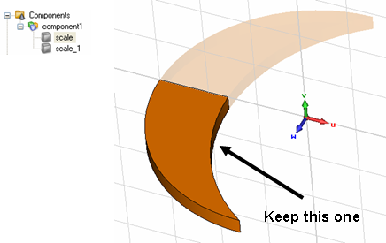
For the electrometers scale, only the original solid is needed; the new one (scale_1) has to be deleted. Please select this shape and delete it either by pressing the Delete key, by selecting Delete from the context menu.
The local coordinate system
will not be used for the following construction steps. Switch it
off by toggling the Modeling:
WCS ![]() Local WCS
Local WCS ![]() .
.
The next step is to rotate
the dielectric solid around the coordinate system's origin by a parameterized
value. Select the solid scale
and open the Transform Selected Object
dialog box by selecting Modeling:
Tools ![]() Transform
Transform ![]() Rotate
Rotate ![]() . The Operation
Rotate should be selected. Enter -angle
as the rotation angle around the z-axis. Make sure that the Shape
center option is deactivated. (If necessary, press the More>>
button to extend the dialog box.) After confirming with OK a new dialog
box appears and asks you to enter a value for the recently introduced
parameter. Set its value to 30
and enter a helpful description text before confirming with OK. The
recently defined parameter appears inside the Parameter
List window which is usually docked at the lower left part
of the user interface.
. The Operation
Rotate should be selected. Enter -angle
as the rotation angle around the z-axis. Make sure that the Shape
center option is deactivated. (If necessary, press the More>>
button to extend the dialog box.) After confirming with OK a new dialog
box appears and asks you to enter a value for the recently introduced
parameter. Set its value to 30
and enter a helpful description text before confirming with OK. The
recently defined parameter appears inside the Parameter
List window which is usually docked at the lower left part
of the user interface.
|
|
|
Next the three edges have
to be blended. To pick these edges, select Modeling: Picks ![]() Picks
Picks ![]() or use the shortcut e to activate
the Pick Edge Mode. The three picked edges are highlighted with a red
color. To apply the blending to these edges enter the Blend
Edges dialog box (Modeling:
Tools
or use the shortcut e to activate
the Pick Edge Mode. The three picked edges are highlighted with a red
color. To apply the blending to these edges enter the Blend
Edges dialog box (Modeling:
Tools ![]() Blend
Blend ![]() ).
Enter 0.1 to the Radius
text field and press the OK button
to apply a blend operation with radius of 0.1 cm to all three edges.
).
Enter 0.1 to the Radius
text field and press the OK button
to apply a blend operation with radius of 0.1 cm to all three edges.
|
|
|
|
The construction steps of the electrometer's pointer are based on the creation of a brick, chamfering its edges, defining a cylinder and applying Boolean operations on intersecting solids.
Initially, a brick of PEC
material has to be created. Therefore, click on Modeling:
Shapes ![]() Brick
Brick ![]() to activate the brick creation mode. Use the Tab
key to enter the coordinates for the min/max corners and height numerically
or press Esc to enter the Brick dialog box immediately. Create
the brick with
to activate the brick creation mode. Use the Tab
key to enter the coordinates for the min/max corners and height numerically
or press Esc to enter the Brick dialog box immediately. Create
the brick with
First corner: X = -3.5, Y = -0.1 (Xmin, Ymin)
Second corner: X = 0.5, Y = 0.1 (Xmax, Ymax)
Height: Zmax = 0.1 (Zmin = 0)
Please change the name to pointer and the material of the brick to PEC by selecting PEC from the Material drop down list. Later in the modeling process, this will enable you to define potentials or charges to the pointer.

The new shape pointer
needs a spike for the visualization. This is accomplished by chamfering
two front edges (see screenshot above). First, the two edges have
to be picked (Modeling:
Picks ![]() Picks
Picks ![]() or shortcut e). Similar to the
blending of the edges of the electrometer's scale, the chamfering is applied
to the currently selected edges. Select Modeling:
Tools
or shortcut e). Similar to the
blending of the edges of the electrometer's scale, the chamfering is applied
to the currently selected edges. Select Modeling:
Tools ![]() Blend
Blend ![]() Chamfer Edges
Chamfer Edges ![]() and enter the Chamfer width of 0.1. Leave the Angle at 45.
Press OK to apply the chamfer
operation and to close the dialog box. The chamfered brick is displayed
in the screenshot below.
and enter the Chamfer width of 0.1. Leave the Angle at 45.
Press OK to apply the chamfer
operation and to close the dialog box. The chamfered brick is displayed
in the screenshot below.

The pointer features a hole
at the origin of the global coordinate system. This hole can be modeled
by defining a cylinder centered on the origin of the global coordinate
system. Please click on Modeling:
Shapes ![]() Cylinder
Cylinder ![]() to launch the Cylinder Creation Mode. Again use the (Shift+)Tab keys to
define
to launch the Cylinder Creation Mode. Again use the (Shift+)Tab keys to
define
the center at X = 0 and Y = 0 and
the radius 0.05.
The cylindric hole should
be as high as the pointer. To ensure this, pick a point (shortcut p or Modeling:
Picks ![]() Picks
Picks ![]() )
from the pointer, e.g. one of two proposed in the next screenshot.
)
from the pointer, e.g. one of two proposed in the next screenshot.

Now that the height is defined, you are requested to define the inner radius of the cylinder. Because no inner radius is needed for this cylinder, press the Esc key to leave the Cylinder Creation Mode. Finally, the Cylinder dialog box opens, enabling you to set the material properties of the cylinder. Please ensure that the Vacuum material is selected from the Material drop down list.
When you confirm with OK, the Shape Intersection dialog box will open and ask you how to handle the intersection with the pointer. Because the created cylinder models the axis hole, the cylinder should be cut away from the pointer. Check the Cut away highlighted shape radio button and confirm with OK.
|
|
|

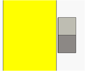
For further simulation purposes
it is useful to have a small distance between the pointer and the scale.
This is, in particular, of interest, when the force or torque on the pointer
is computed. Otherwise the scale would influence and therefore distort
the result of the torque computation. To this end, select the pointer
and enter the transformation dialog box (Modeling:
Tools ![]() Transform
Transform ![]() Translate
Translate ![]() ) to enter a translation of 0.01
in the z-direction. When you switch to a frontal view, e.g. via View:
Change View
) to enter a translation of 0.01
in the z-direction. When you switch to a frontal view, e.g. via View:
Change View ![]() Left, you can see the pointer's distance from the scale:
Left, you can see the pointer's distance from the scale:
The last solid that must
be modeled is the ground. It will be constructed using the extrusion
tool. Pick the face (Modeling:
Picks ![]() Picks
Picks ![]() or shortcut f) of the
dielectric solid (scale) which
is located on the opposite side of the pointer. Then activate the extrusion
tool by selecting Modeling:
Shapes
or shortcut f) of the
dielectric solid (scale) which
is located on the opposite side of the pointer. Then activate the extrusion
tool by selecting Modeling:
Shapes ![]() Extrude
Extrude ![]() . Please name the solid ground,
set the Height to 0.1
and set the Material to PEC in the appearing Extrude
Face dialog box.
. Please name the solid ground,
set the Height to 0.1
and set the Material to PEC in the appearing Extrude
Face dialog box.
|
|
|
The structures modeling is now complete.
For proper function of the electrometer, a voltage source between the two PEC regions must be defined. This can be accomplished with two potential definitions.
Activate the potential tool (Simulation:
Sources and Loads ![]() Electric Potential
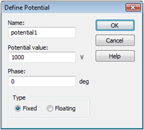
Electric Potential ![]() ), double-click on the pointer
solid and press the Enter key
to define the Potential value
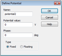
of 1000V. Similarly, set the
ground potential to 0
V. Please note that the definition of the second potential is necessary
to calculate the capacitance matrix (only potentials will be considered
for the capacitance matrix). The screenshot below shows the structure
with the potential settings of the electrometer's ground and pointer.
), double-click on the pointer
solid and press the Enter key
to define the Potential value
of 1000V. Similarly, set the
ground potential to 0
V. Please note that the definition of the second potential is necessary
to calculate the capacitance matrix (only potentials will be considered
for the capacitance matrix). The screenshot below shows the structure
with the potential settings of the electrometer's ground and pointer.

Please note: All
PEC regions that are not assigned with a source will, by default, be given
a potential of 0 V internally unless they touch another PEC region with
a defined potential. In the latter case this defined potential is used
for the internal potential setting. The implicitly set potentials
are not visualized in this view. You can change this default behaviour
of sourceless PEC regions in the Specials
dialog box of the electrostatic solver (Simulation:
Solver ![]() Start Simulation
Start Simulation ![]() ) from Grounded
to Floating meaning that all
PEC regions to which no source is assigned will be considered like floating
potentials.
) from Grounded
to Floating meaning that all
PEC regions to which no source is assigned will be considered like floating
potentials.
The default setting for the background material has to
be adapted to the problem. Open the Background
Properties dialog box (Simulation:
Settings ![]() Background
Background ![]() ). The Material type
has been set to Normal already
by the project template. Furthermore, a surrounding space of 1cm to the
structure is needed. If not already set, please check the Apply
in all directions check-box and enter a value of 1 in the Distance field. These settings will
lead to a simulation with 1 cm additional vacuum space in each direction.
). The Material type
has been set to Normal already
by the project template. Furthermore, a surrounding space of 1cm to the
structure is needed. If not already set, please check the Apply
in all directions check-box and enter a value of 1 in the Distance field. These settings will
lead to a simulation with 1 cm additional vacuum space in each direction.
Next, the boundary settings are specified. To this end,
open the Boundary Conditions
dialog box via Simulation: Settings ![]() Boundaries
Boundaries ![]() . For the modeled problem, no symmetry conditions can
be used and the device has to be modeled in free space. Thus, all boundary
conditions should be changed from type electric to type open. As long
as the Boundaries tab is open in the Boundary Conditions dialog box, the
currently set boundary conditions are displayed together with the model
in the Modeler View:
. For the modeled problem, no symmetry conditions can
be used and the device has to be modeled in free space. Thus, all boundary
conditions should be changed from type electric to type open. As long
as the Boundaries tab is open in the Boundary Conditions dialog box, the
currently set boundary conditions are displayed together with the model
in the Modeler View:

Model with open boundary conditions
The calculation of the electrostatic fields should be
performed for several pointer angles. Therefore, a parameter sweep
for the previously defined parameter angle will be performed. The
first step is to set the solver parameters. Therefore, launch the
Electrostatic Solver Parameters
dialog box by pressing Simulation:
Solver ![]() Start Simulation
Start Simulation ![]() . With the Mesh
type setting you may choose between a hexahedral or tetrahedral
mesh to discretize the calculation domain. The chapter Tetrahedral
Meshing Strategy will focus on this subject. For the moment,
select Hexahedral Mesh. Please
check the Calculate capacitance matrix
button to enable the capacitance matrix calculation, and disable the Adaptive mesh refinement.
. With the Mesh
type setting you may choose between a hexahedral or tetrahedral
mesh to discretize the calculation domain. The chapter Tetrahedral
Meshing Strategy will focus on this subject. For the moment,
select Hexahedral Mesh. Please
check the Calculate capacitance matrix
button to enable the capacitance matrix calculation, and disable the Adaptive mesh refinement.
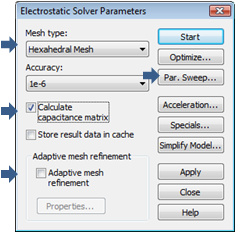
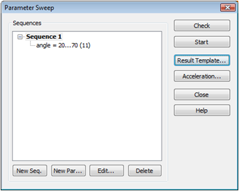
Continue with setting up the parameter sweep by pressing the Par. Sweep... button. The Parameter Sweep dialog box opens and the Electrostatic Solver Parameters dialog box is closed. First, you should add a sweeping sequence by clicking on the New seq. button. Then Sequence 1 appears in the Sequences frame. Next the sweeping parameter has to be added to the newly defined sequence. Clicking on the New Par... button leads you to the Parameter Sweep Parameter dialog box.
Please choose the parameter angle from the Name drop list and check the Sweep checkbox in this dialog window. Now you can enter the range that is used for the variation of the parameter by typing 20 in the From field and 70 in the To field. In addition, enter 11 in the Steps field. These settings indicate that the pointer angle is varied from 20° up to 70° in steps of 5° when the parameter sweep is running.
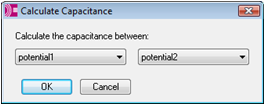
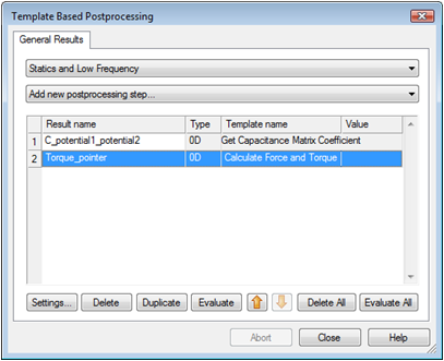
Finally, add the results of interest which should be recorded by the parameter sweep from the individual calculations; this will allow a comparison of the different calculations with regard to the parameter value. To this end, click the Result Template... button. In the Template Base Postprocessing dialog box, which will pop up automatically, select the template group Statics and Low Frequency and the postprocessing step Get Capacitance Matrix Coefficient. Now you can define different combinations of the defined potentials, each representing one coefficient in the capacitance matrix. In this example, we focus on the capacitance between potential1 and potential2. Confirm this setting with OK.
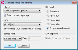
A second watch is used in this tutorial to analyze the torque on the pointer for a moment axis in the positive z-direction from the coordinate axis origin. Therefore, select Calculate Force and Torque from the Add new postprocessing step... drop down list to open the dialog box for the force and torque calculation. Select the pointer solid from the Object drop down list (component1:pointer) and Torque around z/w-axis in the 0D-Result frame. The default axis (0,0,1) and origin (0,0,0) will be used for the torque computation. Finally, select the E-Static Field in the Source Field frame. Due to the distance between the pointer and the scale, the pointer is completely surrounded by background material so that the state of the checkbox Extend to touching shapes has no influence on the result in this case. Confirm these settings with OK.
The Template Based Postprocessing dialog box should now contain two entries:
Leave this dialog box with the Close button. Back in the Parameter Sweep dialog box, press the Start button of the Parameter Sweep dialog box. The results are generated in several solver runs with the structure modified by the parameter variation. After the simulation process is finished you can leave the Parameter Sweep by pressing the Close button.
Please note that the results might differ slightly depending on the operating system and the architecture of the machine with which they were computed.
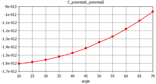
One of the main results is the capacitance between pointer
and ground. This result is automatically generated by the capacitance
watch and can be accessed under the Tables
folder in the navigation tree. There you can select Tables
![]() 0D Results
0D Results ![]() C_potential1_potential2 to view
the capacitance plotted vs. the pointer angle. It can be seen that
the geometry results in a quadratic variation in the capacitance as a
function of angle.
C_potential1_potential2 to view
the capacitance plotted vs. the pointer angle. It can be seen that
the geometry results in a quadratic variation in the capacitance as a
function of angle.
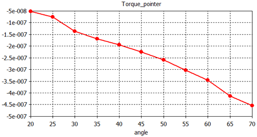
The strong relationship between capacitance and torque
leads to a linear torque with respect to the angle. This allows the
use of this device as a measuring instrument. Select Tables
![]() 0D Results
0D Results ![]() Torque_pointer in the Navigation Tree to view the torque
plotted vs. the pointer angle.
Torque_pointer in the Navigation Tree to view the torque
plotted vs. the pointer angle.
A static field calculation is mainly affected by two sources of numerical inaccuracies:
Numerical errors introduced by the iterative linear equation system solver.
Inaccuracies arising from the finite mesh resolution.
In the this section we provide hints on how to minimize these errors and achieve highly accurate results.
CST EM STUDIO uses an iterative linear equation system solver to solve the discretized field problem. This means that the iterative solver will stop a calculation when a given accuracy is reached. Generally, the default accuracy setting of 1e-6 is sufficient for most calculations. In some cases, however, the solver will give you a warning that results are inaccurate and that you should consider increasing the solver accuracy.
Inaccuracies arising from the finite mesh resolution are usually more difficult to estimate. The only way to ensure the accuracy of the solution is to increase the mesh resolution and recalculate the results. When they do not change significantly anymore as the mesh density is increased, then convergence has been achieved.
In the above example, you have used a modified default
mesh. The easiest way to test the accuracy of the results is to use
the fully automatic mesh adaption that can be switched on by checking
the Adaptive mesh refinement
option in the Electrostatic Solver Parameters
dialog box (Simulation:
Solver ![]() Start Simulation
Start Simulation ![]() ). When you activate the adaptive mesh refinement
and restart the solver, several solver passes will be performed. Finally,
you can visualize the maximum difference of the energy error for two subsequent
passes by selecting 1D Results
). When you activate the adaptive mesh refinement
and restart the solver, several solver passes will be performed. Finally,
you can visualize the maximum difference of the energy error for two subsequent
passes by selecting 1D Results ![]() Adaptive Meshing
Adaptive Meshing ![]() Error from the navigation tree.
Error from the navigation tree.
In this example, the energy deviation between the first and the second pass is about 4%, which indicates that the adaptive mesh refinement was required here to obtain highly accurate results. Generally speaking, global results like energies are less susceptible to discretization errors than local results like field values.
When analyzing the refined mesh (Simulation:
Mesh ![]() Mesh View
Mesh View ![]() ), you should note
that it has been refined particularly around the pointer's edges and in
the z-direction inside the dielectric scale.
), you should note
that it has been refined particularly around the pointer's edges and in
the z-direction inside the dielectric scale.

This knowledge can be used to improve the expert-based mesh manually. A manually refined mesh offers the advantage of saving computation time because the mesh adaptation can be switched off for the next parameter sweep. Because fields change rapidly on the pointer's edges and not inside the pointer's volume, it is advisable to apply an edge refinement to this body. In contrast, the mesh adaptation refined the mesh inside the dielectric scale in the z-direction. Therefore, it is convenient to specify a maximum z-step-width inside the scale solid.
Select the pointer in the navigation tree select Local Mesh Properties from the context menu. In the Local Mesh Properties dialog box for this solid, activate the checkbox Use Edge refinement factor and increase its refinement value to 10:

To refine the mesh inside the scale solid, select it in the navigation tree, choose Local Mesh Properties from the context menu and enter a maximum step-width value of 0.02 in the z-direction (Dz):

The manually refined mesh includes the information extracted from the previous adaptation sequence. It has been sufficiently refined and you may therefore enter the solver dialog box again and switch off the adaptive mesh refinement. When you start the parameter sweep with the improved mesh, you will notice that the capacitance curves have not changed significantly, while the torque curve now meets the expectations much better compared to the first sweep:
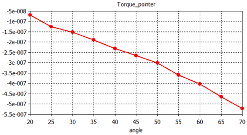
Because field singularities appeared on the pointer's PEC edges, the mesh refinement within these regions allowed the solver to produce more accurate results. On the other hand, these fields are used to compute the pointer's torque. So in this case, you have a global result depending strongly on local field values.
As mentioned above, CST EM STUDIO provides two types of mesh. During the previous chapters you became quite familiar with the hexahedral meshing strategy. To get an impression of the tetrahedral meshing method, we recommend that you read this chapter. A detailed discussion of the different meshing strategies including mesh adaptation can be found as well in the CST EM STUDIO Workflow & Solver Overview manual.
Before you start the tetrahedral simulation, it is advisable
to make a copy of the current project under a different name. Then switch
to "Tetrahedral Mesh" by selecting Simulation:
Mesh ![]() Global Properties
Global Properties ![]() Tetrahedral. In the Tetrahedral
Mesh Properties dialog box please change the Min.
number of steps value to 10
and confirm your settings by clicking the OK
button. When you now enter the Electrostatic
Solver dialog box (Simulation:
Solver
Tetrahedral. In the Tetrahedral
Mesh Properties dialog box please change the Min.
number of steps value to 10
and confirm your settings by clicking the OK
button. When you now enter the Electrostatic
Solver dialog box (Simulation:
Solver ![]() Start Simulation
Start Simulation ![]() ), the Tetrahedral
Mesh should be the active Mesh
Type. Start the simulation. A couple of seconds later, the calculations
will be finished and you can examine the tetrahedral mesh and the appropriate
results. To get an impression of the tetrahedral mesh, select Simulation:
Mesh
), the Tetrahedral
Mesh should be the active Mesh
Type. Start the simulation. A couple of seconds later, the calculations
will be finished and you can examine the tetrahedral mesh and the appropriate
results. To get an impression of the tetrahedral mesh, select Simulation:
Mesh ![]() Mesh View
Mesh View ![]() :
:

Although this mesh is relatively coarse, it delivers
a good impression about the fields. Select the Potential
entry from the 2D/3D Results
folder in the navigation tree and take a look at the electric field (2D/3D Results ![]() E-Field) :
E-Field) :
|
|
|
An adaptive mesh refinement is also available for the
tetrahedral meshing method. Reenter the solver dialog box (Simulation:
Solver ![]() Start Simulation
Start Simulation ![]() ) and activate the Adaptive
mesh refinement. Before you restart the solver, enter the adaptive
mesh properties dialog by pressing the Properties
button:
) and activate the Adaptive
mesh refinement. Before you restart the solver, enter the adaptive
mesh properties dialog by pressing the Properties
button:
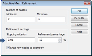
Since the hexahedral adaptation run was able to deliver
a relative error of less than 1%, you may also this time set the convergence
criterion to a value of 0.01. Leave the dialog by pressing the OK
button and start the tetrahedral adaptation run by pressing Start. A
few moments later you can observe the refined mesh by activating the mesh
view (Simulation:
Mesh ![]() Mesh View
Mesh View
![]() ):
):
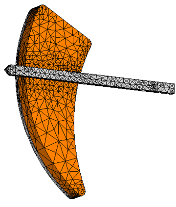
The mesh has been refined roughly at the same locations
where the hexahedral method added new mesh lines, specifically, the surroundings
of the pointer. Finally, examine the adaptation convergence curve
by selecting 1D Results ![]() Adaptive Meshing
Adaptive Meshing ![]() Error from the navigation tree:
Error from the navigation tree:
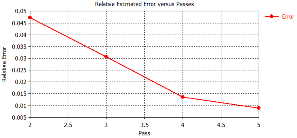
The relative error between two subsequent passes dropped below 1% within 4 calculation passes. Please note that the final results as well as the number of calculation passes can differ slightly depending on the operating system and the architecture of the machine which is used for the simulation.
Congratulations! You have just completed the electrometer tutorial that should have provided you with a good working knowledge on how to use the electrostatic solver. The following topics have been covered:
General modeling considerations, using templates, etc.
Modeling curves using the circle creation tool in combination with trim curves tool.
Creating shapes from planar curves using the extrusion tool.
Model shapes using the cylinder- and brick creation tool.
Applying blend and chamfer operations on existing shapes.
Define potentials on PEC solids.
Define boundary conditions.
Setup the electrostatic solver.
Setup of parameter sweep watches.
Perform a parameter sweep.
Visualize the results of the parameter sweep.
Obtain accurate and converged results using the automatic mesh adaptation.
Get a first impression of the tetrahedral meshing method.
You can obtain more information for each particular step from the online help system that can be activated either by pressing the Help button in each dialog box or by pressing the F1 key at any time to obtain context sensitive information.
In some instances, we have referred to the CST EM STUDIO Workflow & Solver Overview manual that is also a good source of information for general topics.
In addition to this tutorial you can find more electrostatic calculation examples in the Examples folder in your installation directory. Each of these examples contains a Readme item in the navigation tree that will give you more information about the particular device.
And last but not least: Please also visit one of the training classes, held regularly at a location near you. Thank you for using CST EM STUDIO.