This example shows the calculation of the capacitance matrix for a RJ45 connector. The model consists of the connector and the corresponding socket, each containing eight wires for the signal transmission. The wires of the socket are fixed to a substrate plate. The remaining wires are connected to a metallic ground plane. This provides some kind of shielding effect for the transmission of the wire signals.
The structure is modelled in general by defining specific curves and finally extrude them to solid shapes. Hereby the advantage of the local coordinate system is used to determine the relative locations of the different created shapes. Identical elements are mirrored or multiplied and the loft functionality enables the construction of smooth strip line gradients.
To start the electrostatic solver potentials at the ground plane and the wires of the socket are defined. The hexahedral solver is selected using default accuracy (1e-6). Adaptivity is switched off. Open boundary conditions are used in this example to approximate an infinitely expanded vacuum space around the connector.
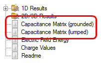
After the calculation, the electric field, electric flux density and the potential distribution of this calculation can be accessed in subfolders of "2D/3D Results" in the navigation tree. In addition both - lumped and grounded -capacitance matrices can be observed by opening the text notes in the navigation tree. In this case the lumped capacitances are probably of more interest:
|
|
|
The capacitance information can be found in the navigation tree below the field results. |