![]()
![]()
Coils in CST EM STUDIO are closed stranded conductors with a homogeneous current distribution in its cross section. They can be driven by either a voltage or a current source.
The geometry of a coil is defined in the coil definition mode. Afterwards the coil dialog box is opened in order to define further settings.
Name
Defines the name of the current or voltage coil. Each coil must have a unique name.
Conductor Type
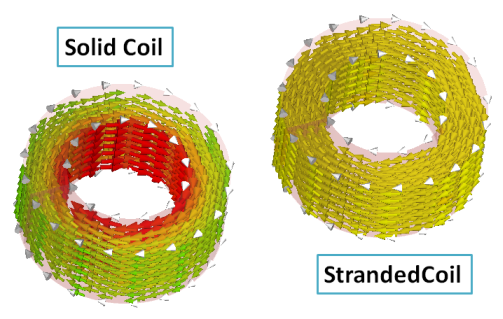
In the Conductor Type drop-down list, you can choose between stranded and solid conductors. A stranded conductor creates a homogeneous current density in the coil's cross section whereas a solid conductor has a constant voltage drop for all turns.
Current / Voltage
Specifies the current or voltage value for the source. For frequency domain calculations it can be specified in the LF Frequency Domain Solver Settings, whether the source value is to be interpreted as peak- or RMS-value. With the default settings, the prescribed current is interpreted as RMS value, i.e. as the root-mean-square values.
Note: Currently not all conductor- / value-type combinations are supported. The following table shows which coil types can be defined:
|
|
Stranded |
Solid |
|
Current |
yes |
yes |
|
Voltage |
yes |
no |
Phase
Specifies the phase of the source value in degrees. Please note that the phase only affects the simulation for frequency domain problems.
Number of turns
Specifies the number of turns for the coil. The flux created by a current coil is proportional to the number of windings.
Resistance
Specifies the Ohmic resistance of the coil.
Note: If voltage driven coils are used for magnetostatic calculations, the Resistance value must not be zero.
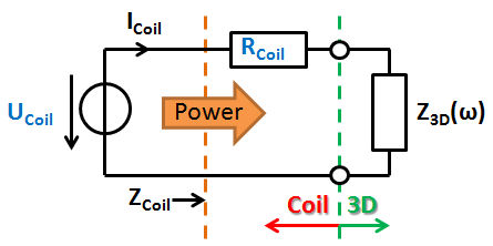
Schematic for a voltage-driven coil: The user given parameters U and R are drawn blue.
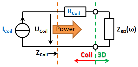
Schematic for a current-driven coil: The user given parameters I and R are drawn blue.
The dashed orange lines indicate the reference plane where coil-impedance and power are computed. The dashed green lines show where the rest of the 3D structure begins. The impedance Z3D represents the coupling from the 3D structure - this value represents the self inductance as well as mutual coupling to the rest of the structure. Z3D can have active character if another source induces a voltage on the coil.
Note: In magnetostatic calculations Z3D is always zero.
After the simulation was finished, all important coil parameters are available in the navigation tree under "Coil Parameters".
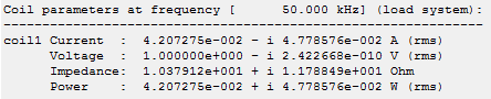
Coil parameters for a voltage driven coil (1 V rms).
Note: The grey arrows on the coil indicate the reference direction of the coil-current, for both coil- and voltage-driven coils. E.g., if a current-driven coil has a source value of 1 A and a phase of 0 degrees the source current density field points into the direction of the grey arrows at a plot phase of 0 degrees:
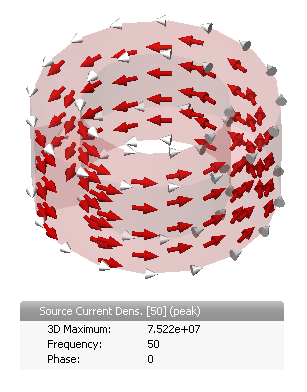
Source current density for a current driven coil (value: 1A phase: 0 degrees).
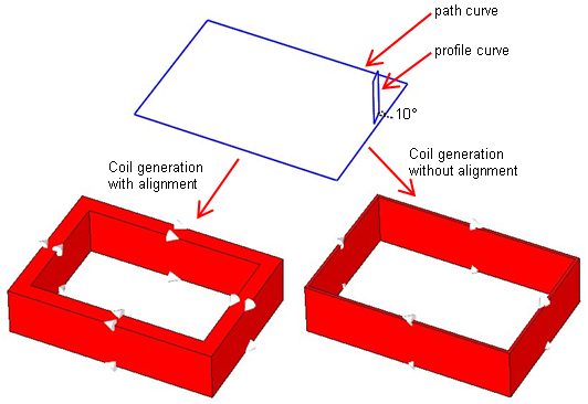
Project profile to path
If this checkbox is activated the profile is aligned with the plane which is normal to the path curve. In the following example you can see the profile which includes an angle of 10 degree with the path curve. The coil on the left hand side will be obtained if the alignment is activated. To generate the coil displayed on the right hand side, the alignment is switched off so that the profile is swept unchanged along the path curve.
OK
Accepts the changes and closes the dialog.
Cancel
Closes this dialog box without performing any further action.
Help
Shows this help text.
See also
Define Current Coil Mode, Magnetostatic Sources