|
|
|
| 首页 >> CST教程 >> CST2013在线帮助系统 |
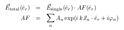
Farfield Calculation of Antenna Arrays
|
|
Single Patch Antenna |
|
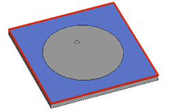
Array Pattern of Six Identical Elements |
|
|
|
|
Rectangular array
Activate this check button to define a rectangular antenna array (linear: 1D; planar: 2D; cubic: 3D). Afterwards, you still have the possibility to modify the resulting array list by changing the element's settings or by removing or adding specific elements.
Edit antenna list
This check button offers the possibility of entering an antenna array manually or of modifying a previously calculated antenna list while the input facilities for rectangular arrays are disabled. In the list, it is possible to modify or delete existing antenna elements or create some new ones and add them to the list.
Rectangular array frame
A complete rectangular array may be calculated automatically just by defining the following values. Note that this frame is enabled when the corresponding check button above is activated. The array setup uses automatically the unit cell geometry and phasing if unit cell or periodic boundary conditions are active.
Direction: Specifies the orientation of the rectangular array.
Number: Defines the number of single antenna elements in each coordinate direction.
Spaceshift: Defines the constant space shift between two antenna elements in the respective coordinate direction.
Phaseshift: Defines the constant phase shift between two antenna elements in the respective coordinate direction.
Update antenna list: Evaluates the complete antenna list of the rectangular array defined by the given values and shows it in the listbox below. The single antennas are characterized by their location in space (x, y, z) as well as by their amplitude and phase information.
Antenna list frame
Displays the current antenna list of the array pattern. If the list is activated single antenna elements can be modified, deleted or created in order to define an arbitrary array pattern. Note that this frame is enabled when the corresponding check button above is activated.
No.: A unique number is assigned to each antenna array element.
X,Y,Z: These values show the spatial location of each array element.
Amplitude: Shows the amplitude of each array element. Using the automatic calculation for a rectangular array the default for the amplitude of all elements is one.
Phase: Shows the given phase information of each array element.
Modify...: Opens a dialog window for changing the position, the amplitude or the phase properties of a selected antenna element.
Add...: Offers the possibility to add a new single antenna element to the given array list by defining its position as well as the amplitude and phase properties.
Delete: Deletes a selected element of the given antenna list.
OK
Confirming the OK button will plot the farfield result of the current antenna list. If the editing possibility is activated, the momentarily shown list is used for calculation ignoring the settings of the Rectangular Array dialog.
Cancel
Leaving the Farfield Array dialog without saving any changes. The previously made settings are maintained.
Help
Shows this help text.
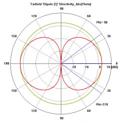
Example
|
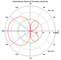
Farfield polar plot of a l/2-dipole antenna. |
|
Farfield polar plot of a linear array with two elements of the dipole antenna shown left exhibiting a spaceshift of l/4 and a phaseshift of 90 degrees. |
|
|
|
|
See also
Farfield Plot, Farfield View, Color Ramp


HFSS视频教程 ADS视频教程 CST视频教程 Ansoft Designer 中文教程
|
Copyright © 2006 - 2013 微波EDA网, All Rights Reserved 业务联系:mweda@163.com |
|