|
微波射频仿真设计 |
|
|
微波射频仿真设计 |
|
| 首页 >> Ansoft Designer >> Ansoft Designer在线帮助文档 |
|
System Simulator > Step 2: Extracting the Discrete Time Impulse and Noise ResponsesIn general, a bandpass impulse response may be written in the following form:
where,
as in the case of signals, the quantity
For a linear electrical sub-design with N input ports and M output ports (see Figure 5
above), the number of impulse responses needed for discrete time simulation
is given by To extract the equivalent set of discrete time bandpass
impulse responses, the principle of superposition is used whereby the
voltages at the external output ports (

where the frequency vectors It can be shown that the equivalent set of discrete time bandpass impulse responses can be obtained in this case using the following transformations:
where: 

and

As mentioned above, for a linear electrical sub-design
with M output ports, the
number of discrete time noise responses needed for simulation is M. For each external output
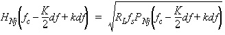
port, the total noise power contribution from all input ports and the
system PNj(f) at the jth external
output port ( Since the noise at the external output ports is typically colored (i.e., filtered) Gaussian noise, discrete time simulation of an electrical sub-design involves extracting the equivalent noise filter response needed to color the input white Gaussian noise. It can be shown from the statistical theory of random processes, that the noise filter response is described by the following complex envelope at the carrier frequency fc:
where: 

HFSS视频教程 ADS视频教程 CST视频教程 Ansoft Designer 中文教程 |
|
Copyright © 2006 - 2013 微波EDA网, All Rights Reserved 业务联系:mweda@163.com |
|

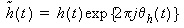 = The baseband complex envelope impulse response
of the bandpass impulse response.
= The baseband complex envelope impulse response
of the bandpass impulse response.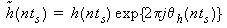 ,
, 
 and the number of noise responses
is given by
and the number of noise responses
is given by  ,
,  ) are evaluated
  Volts and
 Volts,
  ,
, ,
,
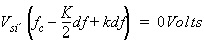
 ). These voltages are obtained by means of
solving the following set of KCL linear equations:
). These voltages are obtained by means of
solving the following set of KCL linear equations:
 and
and  represent the nodal voltages and currents
in the system at frequency
represent the nodal voltages and currents
in the system at frequency 

 ) is computed at the same discrete
frequency points used for the sub-design impulse response evaluation.
This total noise contribution includes the passive and active noise
contributed by the entire sub-design.
) is computed at the same discrete
frequency points used for the sub-design impulse response evaluation.
This total noise contribution includes the passive and active noise
contributed by the entire sub-design.