|
微波射频仿真设计 |
|
|
微波射频仿真设计 |
|
| 首页 >> Ansoft Designer >> Ansoft Designer在线帮助文档 |
|
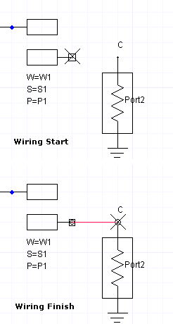
Schematic Editor > The Schematic Editor WindowThe Schematic Editor window allows you to place components and wire them together. You can move components by simply selecting and dragging them. Copy and paste can be used on components and their wires within the schematic editor. You can also copy and paste to other schematics. As you place the cursor near a pin of a component, it changes from an arrow to an X. This indicates that the schematic editor is in the wiring mode. In the wiring mode, left-click to start drawing a wire. Left-click again to end the wire.
Commonly used items such as ports, n-port black boxes, grounds, and page connectors can be placed in the schematic by clicking their toolbar icons or by using the Draw menu. View controls to zoom in, zoom out, and fit the drawing to the editor window are available on the View menu, and on the shortcut menu that opens when you right-click in a schematic. The arrow keys scroll the view up, down, left, or right in small increments. The page up and page down keys scroll the view up or down in larger increments. If you scroll so far that no objects are in the view, select Fit Drawing from the View pulldown in the Designer top menu bar (or Ctrl+D) to recenter the entire design, resized to fill the window.
HFSS视频教程 ADS视频教程 CST视频教程 Ansoft Designer 中文教程 |
|
Copyright © 2006 - 2013 微波EDA网, All Rights Reserved 业务联系:mweda@163.com |
|