|
微波射频仿真设计 |
|
|
微波射频仿真设计 |
|
| 首页 >> Ansoft Designer >> Ansoft Designer在线帮助文档 |
|
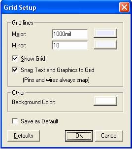
Schematic Editor > Schematic Grid SetupYou can adjust the visibility, color, resolution, and other characteristics of the Schematic editor grid. To access these settings, do either of the following to open the Grid Setup dialog: • On the Schematic menu, click Grid Setup. • On the Schematic toolbar, click
the Grid Setup button
The Grid Setup dialog is used to set visibility, colors, resolutions, and snapping for the Schematic editor’s alignment grid. Grid Lines GroupMajor—This check box specifies the spacing of major grid lines (default in mils). To specify a different value, click in the Major box and type the new value. To change the color of the major grid lines, click the Major color button, specify a color in the Color dialog box, and then click OK Minor—This check box specifies the spacing of minor grid lines (default in mils). To specify a different value, click in the Minor box, and then type the new value. To change the color of the minor grid lines, click the Minor color button, specify a color in the Color dialog box, and then click OK. Show Grid—This check box toggles grid-line visibility. Check Show Grid to make the grid lines visible, or clear Show Grid to turn grid line display off. The default for Show Grid is on/checked. Snap Text and Graphics to Grid —This check box controls whether graphics (arcs, circles, lines, polygons, rectangles, and text) placed near the grid, but not on, will automatically snap upon placement to the nearest grid intersection. The default for Snap Text and Graphics to Grid is on/checked. Other GroupBackground Color—This control sets the background color used for schematic editing. To modify the Background Color, click the color box to open the Color dialog box. Then specify a color and click OK. Save as Default—Check this box to save the current Grid Setup values for use across Designer sessions. • Click Defaults to restore all Grid Setup settings to their installation defaults. • Click OK to commit changes made and close the dialog box. • Click Cancel to close this dialog box without committing any changes.
HFSS视频教程 ADS视频教程 CST视频教程 Ansoft Designer 中文教程 |
|
Copyright © 2006 - 2013 微波EDA网, All Rights Reserved 业务联系:mweda@163.com |
|
 .
.