|
微波射频仿真设计 |
|
|
微波射频仿真设计 |
|
| 首页 >> Ansoft Designer >> Ansoft Designer在线帮助文档 |
|
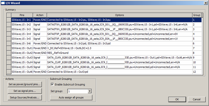
Schematic Editor > I/O Wizard DialogThe I/O Wizard dialog provides a summary of the current Wizard configuration and allows you to perform various actions in order to set up individual pins. Click Schematic > I/O Wizard to open the Wizard dialog.
Upon initialization, the I/O Wizard indicates all the unconnected pins that exist in the current schematic. The above figure shows the Wizard dialog after each pin of a 7-pin SIwave component has been configured. • The Wizard displays the current settings for each pin. • Pins can either be left in the default unassigned state, assigned to a signal pin (driver or receiver), or assigned as a Power/Ground pin. • Select one or more rows and click the various Actions buttons to associate selected pins with a given type. A configuration window will appear that allows further customization. • Power/Ground pins are initially assigned if the component's name contains "VSS", "GND", etc. Initial assignments can be overidden and customized. • When Enable Subcircuit Grouping is selected, pins can be assigned to a group. • Auto assign all groups attempts to group pins in a meaningful way — by grouping buffers with common pins into the same subcircuit group.
Click OK to close the dialog and implement any changes that have been configured.
HFSS视频教程 ADS视频教程 CST视频教程 Ansoft Designer 中文教程 |
|
Copyright © 2006 - 2013 微波EDA网, All Rights Reserved 业务联系:mweda@163.com |
|