|
微波射频仿真设计 |
|
|
微波射频仿真设计 |
|
| 首页 >> Ansoft Designer >> Ansoft Designer在线帮助文档 |
|
Schematic Editor > Adding a New Subcircuit to a Design
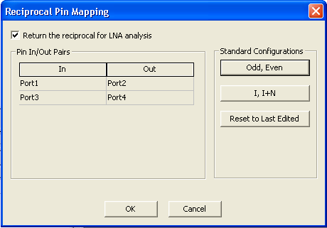
To add a new subcircuit to an existing design: 1. Under Nexxim Circuit or System on the top menu bar, click Add SubCircuit and select the type of subcircuit to add Please note that you must have HFSS, Q3D, or SIwave installed on your system to add a subcircuit from one of these tools. 2. For a schematic subcircuit, the Schematic editor opens. For a Planar EM subcircuit, the Layout editor opens. Use the editor to create the schematic or layout for the subcircuit. You must add ports in the schematic or pins in the layout to provide connections to the outer circuit. 3. An icon for the subcircuit appears in the Project tree, with the designation “U” (for example, “U1” for the first subcircuit created. 4. A symbol for the subcircuit appears in the schematic. Connect the subcircuit to the rest of the circuit as required. 5. Optionally, you can specify that the subcircuit S-parameters will be inverted (returning the reciprocal of the S-matrix) after running LNA, so that the subcircuit can be used for de-embedding. Please note that to invert correctly, the subcircuit MUST have an even number of ports or pins, arranged as input-output pairs. Subcircuits with odd numbers of ports show Not Valid as the value of the LNA Reciprocal property. • Click on the schematic symbol for the subcircuit to open the Property window. • Click on the button in the Value field of the LNA Reciprocal property. If the reciprocal operation is valid for the subcircuit, the button initially reads LNA Reciprocal OFF. The Reciprocal Pin Mapping dialog opens:
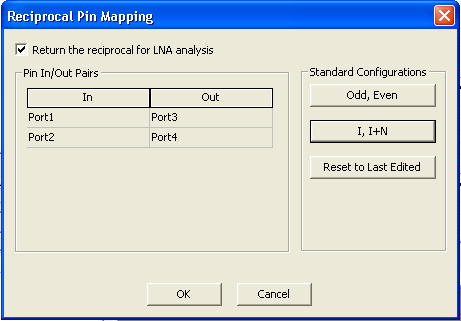
• To enable the reciprocal operation, click the box Return the reciprocal for LNA analysis. • Use the Standard Configurations buttons to select the pin mapping configuration used by your subcircuit. The illustration above shows the Odd, Even configuration with four ports; the odd-numbered ports 1 and 3 are the inputs and the even-numbered ports 2 and 4 are the corresponding outputs. • The figure below shows the I, I+N configuration; now the inputs are ports 1 and 2, while the corresponding outputs are ports 3 and 4.
• Use the Reset to Last Edited button to restore the configuration that was initially read from the schematic. • Click OK to return to the schematic editor. The Value field of the LNA Reciprocal property now reads LNA Reciprocal ON.
HFSS视频教程 ADS视频教程 CST视频教程 Ansoft Designer 中文教程 |
|
Copyright © 2006 - 2013 微波EDA网, All Rights Reserved 业务联系:mweda@163.com |
|