|
微波射频仿真设计 |
|
|
微波射频仿真设计 |
|
| 首页 >> Ansoft Designer >> Ansoft Designer在线帮助文档 |
|
Generating Reports and Postprocessing > Eye MeasurementsSeveral standard eye-diagram measurements are provided in Ansoft Designer. The following eye measurements are supported: • EyeLevelZero • EyeLevelOne • EyeAmplitude • EyeHeight • EyeSignalToNoise • EyeOpeningFactor • EyeWidth • EyeJitterP2P • EyeJitterRMS • EyeRiseTime • EyeFallTime • MinEyeWidth • MinEyeHeight
You can right-click on the report and select Trace Characteristics > Add All Eye Measurements to display all the eye measurements in tabular format. 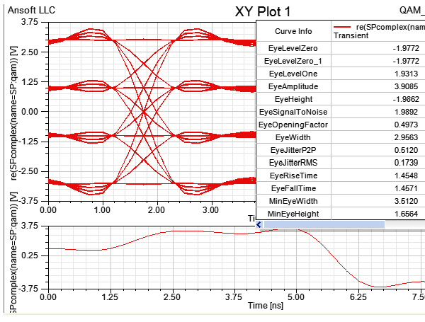
To add an eye measurement, right click on the eye diagram and select one of the following: • Select Trace Characteristics/Add to add eye measurements individually • Select Trace Characteristics/Add All Eye Measurements to add all available eye measurements To remove an eye measurement, right click on the eye diagram: • Select Trace Characteristics/Clear All
Values in the Eye Measurements Table are Calculated as Follows:
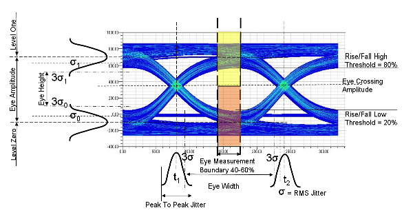
• EyeLevelZero and EyeLevelOne are the mean values of the lower/upper vertical histograms in the 40-60% center region of the eye, where “center” is defined by the eye-crossing points t1 and t2. Vertical histograms are created above/below the eye-crossing point (represented as yellow/orange shaded regions in the figure above). The mean value of these histograms yields EyeLevelZero and EyeLevelOne.
• EyeAmplitude = (EyeAmplitude = EyeLevelOne - EyeLevelZero ). This is the voltage value for the eye crossing point, which is computed by creating a vertical histogram at the eye crossing points. Eye Crossing Amplitude is computed as the mean of the histogram. A front panel eye diagram will have two eye crossings. Eye Crossing Amplitude is calculated as being the mean of these crossing amplitudes, and is then used to compute other horizontal eye measurements, such as eye width, RMS jitter, and peak-to-peak jitter.
• EyeHeight = [(EyeLevelOne - 3σ1) - (EyeLevelZero + 3σ0 )] where σ1 and σ0 are the standard deviations of the vertical histograms used to determine EyeLevelZero and EyeLevelOne.
• EyeSignalToNoise = [ EyeLevelOne - EyeLevelZero ] / ( σ1 + σ0 )
• EyeOpeningFactor = [ EyeAmplitude - σ1 - σ0 ] / EyeAmplitude
• EyeWidth = [( t2 - 3σ) - (t1 + 3σ)] where σ is the standard deviation of the horizontal histograms used to determine eye-crossing points.
• EyeJitterP2P is the width of the horizontal histogram across the eye-crossing point.
• EyeJitterRMS is the standard deviation of the horizontal histogram across the eye-crossing point.
• EyeRiseTime and EyeFallTime are the differences in mean values of the horizontal histograms centered on the 20% and 80% threshold values. Horizontal histograms are created at the 20% and 80% amplitude thresholds for both rising and falling edges. The difference in the mean values of the histograms for rising edges yields EyeRiseTime, while the difference in mean values for falling edges yields EyeFallTime.
• MinEyeWidth is the minimum horizontal opening at the eye-crossing amplitude, typically at the center of the eye. Unlike statistical eye width, if different traces exist for different unit intervals, then MinEyeWidth represents the minimum width of all the traces.
• MinEyeHeight is the minimum vertical opening at the eye-measurement point, typically at the center of the eye. Unlike statistical eye height, if different traces exist for different unit intervals, then MinEyeHeight represents the minimum height of all the traces.
Additional Values Not Listed in the Eye Measurements Table:
• AutoDelay is the amount of time required to shift the eye diagram so that it is centered. You can control this delay either by specifying Manual Delay or you can allow the system to automatically compute the delay via Auto Delay.
• AutoComputeCrossAmplitude
• AutoComputeEyeMeasurementPoint
• EyeCrossingTime is calculated by creating a horizontal histogram across a small, narrow strip at the middle of the eye (eye-crossing points, t1 and t2). Eye Crossing Time is the mean of the histogram. The middle of the eye is computed as the middle of the vertical extremities of the eye — i.e. the midpoint of max & min voltage values across the complete eye diagram. Later, an internal algorithm refines the crossing times by re-computing the crossing points based on a more accurate amplitude. The refined crossing time calculation is then used as the new middle of the eye. A front panel eye diagram will have two eye crossings and two Eye Crossing Times.
• EyeMeasurementPoint (time)
is calculated as the mean of the two eye crossing times in a front panel
eye diagram. This value is then used to compute several vertical eye
measurements, such as eye height, eye amplitude, level one, and level
zero, etc. If Auto Mode is “off”, the user should enter
the time value where he thinks the actual vertical eye measurements
should be conducted (at present, only minimum eye height is measured).
The eye measurements described above can be accessed by analyzing QuickEye simulation in HighSpeedChannel.adsn (Nexxim standard examples) and putting your cursor on AEyeProbe.  The two check boxes will be on the Eye diagram tab of the trace properties: 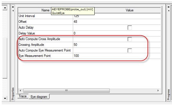
HFSS视频教程 ADS视频教程 CST视频教程 Ansoft Designer 中文教程 |
|
Copyright © 2006 - 2013 微波EDA网, All Rights Reserved 业务联系:mweda@163.com |
|


