|
微波射频仿真设计 |
|
|
微波射频仿真设计 |
|
| 首页 >> Ansoft Designer >> Ansoft Designer在线帮助文档 |
|
Nexxim Simulator > Voltage-Controlled Voltage Source, Polynomial
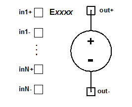 Polynomial VCVS Netlist FormatThe format for a polynomial voltage-controlled voltage source (VCVS) is: Exxxx out+ out- [VCVS] POLY(N) in1+ in1- [in2+ in2- [in3+ in3-]] [MAX=val] [MIN=val] [SCALE=scale] [TC1=val] [TC2=val] [ABS=0|1] p0 [p1 ... pK ] out+ is the positive node and out- is the negative node of the voltage source. The entry VCVS is the default for the E element type. The entry POLY is required to identify the polynomial VCVS type. The number of input voltage pairs, N, can be 1, 2, or 3. If N is not specified, 1 input is the default. in+ and in- are the N pairs of positive and negative nodes for the control voltages. p0 through pK are the K coefficients for the polynomial function. One coefficient must be provided.
Polynomial VCVS Netlist ExamplesE21 21 0 VCVS POLY(1) 1 0 1.1 2.1 0 3.1 E31 31 0 VCVS POLY(2) 1 0 2 0 1.2 2.2 0 0 0 0 0 0 3.2 0 E41 41 0 VCVS POLY(3) 1 0 2 0 3 0 1.3 2.3 0 0 + 0 0 0 0 0 0 + 0 3.3 0 0 0 0 0 0 0 4.3
NotesThe functional equation for the polynomial VCVS is: V(out+) - V(out-) = polynomial ´ SCALE ´ (1 + DT ´ TC1 + DT2 ´ TC2) If the result is less than MIN, V(out+) - V(out-) = MIN If the result is greater than MAX, V(out+) - V(out-) = MAX The polynomial depends on the number of inputs (N) and the number of polynomial coefficients (K). Each polynomial has terms of order (O), the sum of the exponents of the elements in the term. The list of coefficients must include coefficients for every term up to and including the complete group of terms with the highest order in the specified polynomial, using zero coefficients for any intermediate or trailing terms that are not to be computed. When N=1, the polynomial formula has one term each of order O{0, 1, ... K): p0 + p1 ´ V(in1+, in1-) + ... pK ´ V(in1+, in1-)K Each coefficient must be a real value or zero to represent a missing term. For example, to specify a VCVS between nodes 21 and 0 whose output, controlled by a voltage source between nodes 1 and 0, is described by the one-input polynomial 1.1 + 2.1 ´ V(1, 0) + 3.1 ´ V(1, 0)3, the instance statement would set coefficients p0=1.1, p1=2.1, p2=0, and p3=3.1: E21 21 0 VCVS POLY(1) 1 0 1.1 2.1 0 3.1 When N=2, the polynomial formula can have more than one term in each order grouping: O(0) p0 + O(1) p1 ´ V(in1+, in1-) + p2 ´ V(in2+, in2-) + O(2) p3 ´ V(in1+, in1-)2 + p4 ´ V(in1+, in1-) ´ V(in2+, in2-) + p5 ´ V(in2+, in2-)2 + O(3) p6 ´ V(in1+, in1-)3 + p7 ´ V(in1+, in1-)2 ´ V(in2+, in2-) + p8 ´ V(in1+, in1-) ´ V(in2+, in2-)2 + p9 ´ V(in2+, in2-)3 + O(4) ... If the polynomial includes any terms from an order group, the list of coefficients must include intermediate and trailing zeros to complete the order. For example, to specify a VCVS between nodes 31 and 0, whose output is controlled by voltages across node pairs (1, 0), and (2, 0), is described by the two-input polynomial 1.2 + 2.2 ´ V(1, 0) + 3.2 ´ V(1, 0) ´ V(2, 0)2, the instance statement would set coefficients p0=1.2, p1=2.2, and p8=3.2. Intermediate coefficients p2 through p7 and trailing coefficient p9 are set to 0: E31 31 0 VCVS POLY(2) 1 0 2 0 1.2 2.2 0 0 0 0 0 0 3.2 0 When N=3, the polynomial formula becomes: O(0) p0 + O(1) p1 ´ V(in1+, in1-) + p2 ´ V(in2+, in2-) + p3 ´ V(in3+, in3-) + O(2) p4 ´ V(in1+, in1-)2 + p5 ´ V(in1+, in1-) ´ V(in2+, in2-) + p6 ´ V(in1+, in1-) ´ V(in3+, in3-) + p7 ´ V(in2+, in2-)2 + p8 ´ V(in2+, in2-) ´ V(in3+, in3-) + p9 ´ V(in3+, in3-)2 + O(3) p10 ´ V(in1+, in1-)3 + p11 ´ V(in1+, in1-)2 ´ V(in2+, in2-) + p12 ´ V(in1+, in1-)2 ´ V(in3+, in3-) + p13 ´ V(in1+, in1-) ´ V(in2+, in2-)2 + p14 ´ V(in1+, in1-) ´ V(in2+, in2-) ´ V(in3+, in3-) + p15 ´ V(in1+, in1-) ´ V(in3+, in3-)2 + p16 ´ V(in2+, in2-)3 + p17 ´ V(in2+, in2-)2 ´ V(in3+, in3-) + p18 ´ V(in2+, in2-) ´ V(in3+, in3-)2 + p19 ´ V(in3+, in3-)3 + O(4) ... For example, to specify a VCVS between nodes 41 and 0 whose output, controlled by voltages across node pairs (1, 0), (2, 0), and (3, 0) is described by the three-input polynomial 1.3 + 2.3 ´ V(1, 0) + 3.3 ´ V(1, 0)2 ´ V(2, 0) + 4.3 ´ V(3, 0)3, the instance statement would set coefficients p0=1.3, p1=2.3, p11=3.3, and p19=4.3. Intermediate coefficients p3 through p10 and p12 through p18 are set to 0 (since p19 is the coefficient for the highest term with order 3, no trailing zero coefficients are needed): E41 41 0 VCVS POLY(3) 1 0 2 0 3 0 1.3 2.3 0 0 + 0 0 0 0 0 0 + 0 3.3 0 0 0 0 0 0 0 4.3
HFSS视频教程 ADS视频教程 CST视频教程 Ansoft Designer 中文教程 |
|
Copyright © 2006 - 2013 微波EDA网, All Rights Reserved 业务联系:mweda@163.com |
|


