淘宝官方店     推荐课程     在线工具     联系方式     关于我们  


微波射频仿真设计   Ansoft Designer 中文培训教程   |   HFSS视频培训教程套装


Agilent ADS 视频培训教程   |   CST微波工作室视频教程   |   AWR Microwave Office

          首页 >> Ansoft Designer >> Ansoft Designer在线帮助文档


Ansoft Designer / Ansys Designer 在线帮助文档:


Nexxim Simulator >
Nexxim Component Models >
MOSFET Levels 55 through 99 >
   MOSFET Instance, BSIM3-SOI Model (Level 57)       

MOSFET Instance, BSIM3-SOI Model (Level 57)


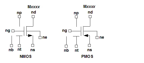
BSIM3-SOI MOSFET Instance Netlist Syntax

The syntax for a LEVEL=57 BSIM3-SOI v2.0.1 MOSFET instance is:

Mxxxx nd ng ns ne [np] [nb] modelname [L=length] [W=width]

[AD=val] [AS=val] [PD=val] [PS=val]

[NRD=val] [NRS=val] [NRB=val] [RTH0=val] [CTH0=val]

[NBC=val] [NSEG=val] [PDBCP=val] [PSBCP=val]

[AGBCP=val] [AEBCP=val] [TNODEOUT=val]

[FRBODY=val] [BJTOFF=val] [M=val]

nd is the drain node, ng is the front gate node, ns is the source node, ne is the back gate or substrate node, np is the external body contact node, and nb is the internal body node of the MOSFET. modelname is the name of a BSIM3-SOI MOSFET model defined in a .MODEL statement elsewhere in the netlist.

When the option WL is in effect (on the .OPTION statement), the syntax becomes:

Mxxxx nd ng ns [nb] modelname [width] [length]

[AD=val] [AS=val] [PD=val] [PS=val]

[NRD=val] [NRS=val] [NRB=val] [RTH0=val] [CTH0=val]

[NBC=val] [NSEG=val] [PDBCP=val] [PSBCP=val]

[AGBCP=val] [AEBCP=val] [TNODEOUT=val]

[FRBODY=val] [BJTOFF=val] [M=val]


Level 57 MOSFET Instance Parameters

Instance Parameter

Description

Unit

Default

AD

Drain diffusion area

Meter2

0.0

AEBCP

Parasitic body-to-substrate overlap area for body contact

Meter2

0.0

AGBCP

Parasitic gate-to-body overlap area for body contact

Meter2

0.0

AS

Source diffusion area

Meter2

0.0

BJTOFF

1 = Turn off BJT

None

0

CTH0

Thermal capacitance per unit width

Farad/Meter

1.0e-5

FRBODY

Coefficient of distributed body resistance effects

None

1.0

L

SOI MOSFET channel length

Meter

5.0e-6

M

Multiplier: simulates parallel transistors

None

1.0

NBC

Number of body contact isolation edges

None

0.0

NRB

Number of squares for body series resistance

None

0.0

NRD

Number of squares of drain diffusion for resistance calculations

None

0.0

NRS

Number of squares of source diffusion for resistance calculations

None

0.0

NSEG

Number of segments for channel width partitioning

None

1.0

PD

Drain diffusion perimeter including channel edge

Meter

0.0

PDBCP

Parasitic perimeter length for the body contact at drain side

Meter

0.0

PS

Source diffusion perimeter including channel edge

Meter

0.0

PSBCP

Parasitic perimeter length for the body contact at source side

Meter

0.0

RTH0

Thermal resistance per unit width

Ohm/Meter

0.0

TNODEOUT

Temperature node flag. If TNODEOUT is not specified, specifying four nodes floats the body node, while specifying five nodes sets the fifth node as the external body contact node, and a body resistance is placed between the internal and external terminals (distributed body resistance simulation).

If TNODEOUT is specified, the last node is interpreted as the temperature node. In this case, specifying five nodes floats the device, while specifying six nodes implies a body-contacted case. If seven nodes are specified, the simulation assumes the body-contacted case with an accessible internal body node (thermal coupling simulation).

None

Not present

W

SOI MOSFET channel width

Meter

5.0e-6


Netlist Example

M65 90 91 92 mos33 L=1.2e-6


HFSS视频教学培训教程 ADS2011视频培训教程 CST微波工作室教程 Ansoft Designer 教程

                HFSS视频教程                                      ADS视频教程                               CST视频教程                           Ansoft Designer 中文教程


      Copyright © 2006 - 2013   微波EDA网, All Rights Reserved    业务联系:mweda@163.com