|
微波射频仿真设计 |
|
|
微波射频仿真设计 |
|
| 首页 >> Ansoft Designer >> Ansoft Designer在线帮助文档 |
|
Nexxim Simulator > Elliptic Band Pass Filter
 Netlist SyntaxAn instance of an elliptic band pass filter has three netlist variants: Axxx n1 n2 N=val
[AMAX=val] [AMIN=val] [FA=val]
[FB=val] [R1=val] [R2=val]
[IL=val] COMPONENT=elliptic_bandpass_filter Axxx n1 n2 KP=val
[AMAX=val] [AMIN=val] [FA=val]
[FB=val] [R1=val] [R2=val]
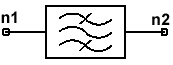
[IL=val] COMPONENT=elliptic_bandpass_filter Axxx n1 n2 FL=val FH=val [AMAX=val] [AMIN=val] [FA=val] [FB=val] [R1=val] [R2=val] [IL=val] COMPONENT=elliptic_bandpass_filter n1 and n2 are the nodes connected to the filter. The entry COMPONENT=elliptic_bandpass_filter is required.
Netlist ExampleA22 1 2 N=5 AMAX=.05 AMIN=40 FA=0.5e9 FB=3e9 Notes1. The elliptic filter model represents three separate components: ELBPF_N, ELBPF_KP, and ELBPF_FS. The parameters N, KP, and FL &FH are mutually exclusive in the syntax. 2. The elliptic filter has equal loss maxima in the pass band and equal loss minima in the stop band. The elliptic filter provides a sharp transition region for the lowest possible order. 3. The magnitude of the transfer function of the elliptic filter (low-pass prototype) is equal to the inverse of the loss:
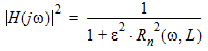
where: Rn(ω, IL) is the Nth-order Chebychev rational function, e = 100.1AMIN, w = 2pf,
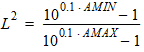
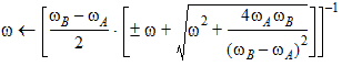
4. The first netlist variant specifies the order of the filter, N. The order defines the number of reactive elements needed to implement the filter. The range for N (order of filter) is from 2 to 15. Orders higher than 15 cannot be simulated. 5. The second netlist variant specifies the sharpness of the filter, KP. The order of the filter is then calculated from the value of KP. 6. The third netlist variant specifies one or both stop band edges, FH and FL. The required order of the filter is calculated from the edge information. 6A. When only FH or FL is given, the edge frequencies are calculated to define a geometrically symmetrical filter: 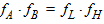
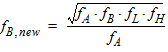
6B. When both FH and FL are given such that
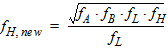
6C. When both FH and FL are given such that

6D. After the edge calculations, the normalized
low-pass model poles are calculated for
References[1] Approximation Methods for Electronic Filter Design, Richard W. Daniels, McGraw-Hill, Inc. [2] Handbook of Filter Synthesis, Anatol I. Zvered, John Wiley & Sons, Inc. 1967.
HFSS视频教程 ADS视频教程 CST视频教程 Ansoft Designer 中文教程 |
|
Copyright © 2006 - 2013 微波EDA网, All Rights Reserved 业务联系:mweda@163.com |
|
 , a new upper stop
band edge and a new upper pass band edge are defined:
, a new upper stop
band edge and a new upper pass band edge are defined: , a new lower stop
band edge and a new lower pass band edge are defined:
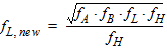
, a new lower stop
band edge and a new lower pass band edge are defined:


