|
微波射频仿真设计 |
|
|
微波射频仿真设计 |
|
| 首页 >> Ansoft Designer >> Ansoft Designer在线帮助文档 |
|
Nexxim Simulator > Chip Inductor with Q Factor
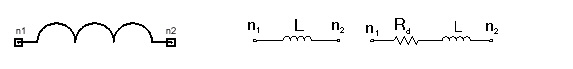 Netlist SyntaxThe general syntax for a chip inductor with Q factor is: Axxxx n1 n2 L=val Q=val FQ=val FRES=val TC=val TEMP=val COMPONENT=chipindq n1 is the positive node and n2 is the negative node of the inductor. The current is assumed to flow from n1 through the inductor to n2. The parameter COMPONENT=chipindq identifies the element as a chip inductor with Q factor.
Inductor Instance Netlist ExampleAchipindq2 1 2 L=5e-9 Q=325 TC=2 COMPONENT=chipindq Notes1. The model is described by the following:  ,
where w=2pf, and f is the operating frequency. 2. If Q is not specified, then the inductor is assumed to be ideal, that is, Rd=0.
HFSS视频教程 ADS视频教程 CST视频教程 Ansoft Designer 中文教程 |
|
Copyright © 2006 - 2013 微波EDA网, All Rights Reserved 业务联系:mweda@163.com |
|


