|
微波射频仿真设计 |
|
|
微波射频仿真设计 |
|
| 首页 >> Ansoft Designer >> Ansoft Designer在线帮助文档 |
|
Nexxim Simulator > Antenna, Parabolic
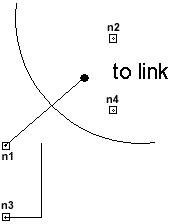 Netlist FormAn instance of a parabolic antenna has the following Nexxim netlist syntax: Axxx n1 n2 n3 n4 D=val [R0=val] COMPONENT=antep n1 and n3 are the nodes connected to the antenna. n2 and n4 are the nodes to be connected to the LINK element for 2-port operation. The entry COMPONENT=antep identifies the element as a parabolic antenna.
Netlist ExampleAantep1 sigout1 sigout2 D1.15 COMPONENT=antep Notes1. The gain of the parabolic antenna is calculated as (pD/l)2, where l is the wavelength. This gain is the maximum antenna gain in the main beam direction. 2. When used as a 1-port or a 2-port, the input impedance is presented by R0 across nodes 1 and 3. When used as a 2-port, the 2nd port should be connected to the LINK element for proper analysis. See note below. 3. The R0 parameter can be used to modify the antenna
calculation reference impedance for non 50-Ohm systems. R0 is used
to convert the antenna’s S References1. C. A. Balanis, Antenna Theory: Analysis and Design, Harper & Row Publishers, Section 7.3, 1982
HFSS视频教程 ADS视频教程 CST视频教程 Ansoft Designer 中文教程 |
|
Copyright © 2006 - 2013 微波EDA网, All Rights Reserved 业务联系:mweda@163.com |
|


