|
微波射频仿真设计 |
|
|
微波射频仿真设计 |
|
| 首页 >> Ansoft Designer >> Ansoft Designer在线帮助文档 |
|
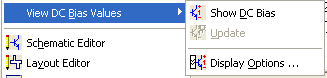
Nexxim Simulator > Viewing DC Bias Voltages and Currents in a SchematicTo run a DC bias analysis on a Circuit design from the Schematic Editor, click on Circuit and select View DC Bias Values from the pulldown menu. A submenu appears:
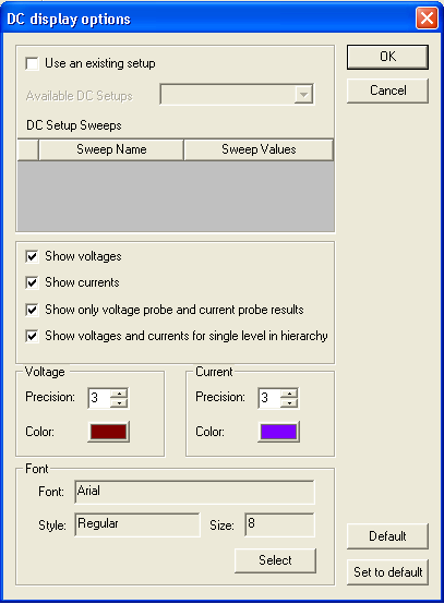
Select Show DC Bias to run the analysis and display the results on the schematic. To remove the DC bias information from the schematic, toggle Show DC Bias. After the first DC bias analysis has been run, select Update to recalculate the bias values after making changes to the circuit. Select Display Options to open the DC display options dialog:
Click Use an existing setup to use the setup information from a DC solution setup that you have already created. Select the setup by name from the pulldown in Available DC Setups. Use the DC Setup Sweeps panel to select a sweep from the existing setup, and to select one of the sweep values for the DC bias analysis. (To run the sweep through all the values, you must perform the DC analysis as described in Running Nexxim DC Analysis from the Schematic Editor.) By default, the DC bias display shows values only for voltage and current probes. However, if the circuit does not contain any probes, Nexxim advises you to adjust the options. Deselect Show only voltage probe and current probe results to enable DC analysis to display values for all nodes. Use the Show voltages and Show currents optionsto display voltages only, currents only, or both voltages and currents. By default, the DC bias information for only a single level of hierarchy is displayed. Toggle this option off to show the information for all levels of a hierarchical design. Use the Voltage and Current panels to control the precision (number of decimal points) and color used to display these values. Use the Font panel to control the font used for the display. Click the Select button to open the Font dialog. Use the sliders to select the desired Font, Style, and Size, then click OK to return to the DC display options dialog. Click Default to restore the default option values in the dialog. Click Set to default to make the currently-set options the defaults. Click OK to enable the specified options, or click Cancel to close the dialog without changing any options.
HFSS视频教程 ADS视频教程 CST视频教程 Ansoft Designer 中文教程 |
|
Copyright © 2006 - 2013 微波EDA网, All Rights Reserved 业务联系:mweda@163.com |
|