|
微波射频仿真设计 |
|
|
微波射频仿真设计 |
|
| 首页 >> Ansoft Designer >> Ansoft Designer在线帮助文档 |
|
Nexxim Simulator > TV Noise Technical NotesSources of Noise The noise output Onoise is a combination of thermal, shot, and flicker noise. Thermal noise is a variation in current due to random thermal motion of the electrons in physical resistors and bulk materials. Thermal noise is directly proportional to the absolute temperature. Shot noise is a fluctuation in the current across P-N junctions in diodes and transistors due to random barrier crossings by electrons and holes in the vicinity of the junction. Shot noise is associated with a direct current flow. Flicker noise is a random variation in current associated with contamination and crystal defects in semiconductors. Like shot noise, flicker noise is associated with a flow of direct current. Flicker noise generates a noise signal with energy concentrated at low frequencies; because of this 1/f frequency dependence, flicker noise is also called 1/f noise. Noise Spectrum The noise spectrum consists of the power spectrum of the coefficients for the harmonic frequencies. The large-signal periodic steady-state of a circuit can be represented by the Fourier equation derived in harmonic balance. In a single large-signal circuit, the one-tone periodic steady state transfer function can be represented by the equation: 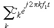
Where k is the harmonic number The small-signal AC perturbation can be represented by the equation: 
Where A is a constant and fi is the small-signal frequency. The output response of the circuit is the product of the small-signal perturbation and the large-signal transfer function. The response can be represented by the equation: 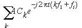
The frequency of the response has been shifted by fi. When constant A is normalized to 1 (one), the coefficient Ck gives the magnitude of the response at harmonic k. In a circuit with two large-signal tones f1 and f2, the periodic steady state can be represented by the equation: 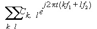
Where k is the harmonic number for frequency f1 and l is the harmonic number for frequency f2. The response of this circuit to the small-signal perturbation above can be represented by the equation: 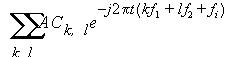
The frequency of the response has again been shifted by fi. When constant A is normalized to 1 (one), the coefficient Ck,l gives the magnitude of the response at the frequency that combines harmonic k of f1 and harmonic l (letter l) of f2. Noise Computation Formulas The calculation of the noise frequencies is a multi-step procedure. First, a set of output frequencies is generated from the swept output frequencies by applying the offsets from the RELHARMVEC list to the (n) corresponding frequencies from the SS_TONES list.

Here is an example that shows how the offsets work. Suppose the desired output frequencies are 1001Hz, 1010Hz, and 1100Hz. This sequence could be specified using the POI sweep specification. However, this example uses the RELHARMVEC offset to calculate the desired frequencies. (Since only one offset is required, the example could use RELHARMNUM instead of RELHARMVEC.) .TV_NOISE The decade (DEC) sweep generates Fswept values of 1, 10, and 100. An input frequency is calculated for each swept value. In this example with one SS_TONES frequency, there is only one product: (relharmvec[1] × SS_TONES[1]) = (1 × 1000) = 1000. Then: Foutput[1] = 1 + 1000 = 1001 Foutput[2] = 10 + 1000 = 1010 Foutput[3] = 100 + 1000 = 1100 The default for RELHARMVEC is a vector of zeros; with this value, the output frequencies are just the swept frequencies. For the gain calculation, Nexxim TV Noise computes the input frequency Finput at each of the values of the output frequency Foutput by adding sum of the products of each of the (n) steady-state frequencies FSS_TONES multiplied by the corresponding REFSIDEBAND coefficient:
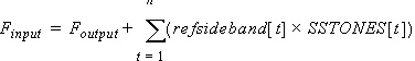
Here is a simplified example. This example uses a single output frequency. .TV_NOISE The resulting calculation would be: SUM1 = (0 × 1000) + (0 × 2000) + (0 × 3000) = 0 Foutput = Fswept + SUM1 = 1000000 + 0 = 1000000 SUM2 = (-1 × 1000) + (1 × 2000) + (2 × 3000) = 7000 Finput = Foutput + SUM2 = 1000000 + 7000 = 107000 Typically, the sweep specification generates several output frequencies, perhaps using RELHARMVEC coefficients other than zero. The Onoise output vector is calculated for the specified output devices at the output frequencies. Nexxim combines the harmonic frequencies (from -SS_MAXK to +SS_MAXK, plus 0) of each of the steady-state tones (specified by SS_TONES) with the output frequencies to calculate a vector of internal noise frequencies that can contribute to the Onoise output.
The formula is too complicated to write explicitly. Here is a numerical example. .TV_NOISE Using the default for RELHARMVEC, Foutput is just the swept frequency, one megahertz. The Fonoise vector is calculated for every combination of harmonics (-1, 0, +1) for the 1001-Hz steady-state tone and harmonics (-2, -1, 0, +1, +2) for the 20000-Hz steady state tone. The resulting vector would have (3 × 5) = 15 elements: 1000000 + (0 ×
20000) + (0 ×
1001) = 1000000 Nexxim then calculates the noise output at these frequencies. Periodic Transfer Function Computation Formulas The netlist must specify the combination of harmonics of the steady state SS_TONES frequencies, using either MAXSIDEBAND or SIDEBAND. When the SS_TONES list has only one frequency, you can use the MAXSIDEBAND entry to specify the maximum harmonic of that frequency. The input frequencies will be calculated using the formula: Finput = Foutput + {-K × f1 to K × f1} Where Foutput is the output frequency (possibly swept), K is the value specified for MAXSIDEBANDS, and f1 is the frequency specified in the SS_TONES entry. Alternatively, you can specify a set of specific sidebands to use for the single output frequency, using the SIDEBAND entry. For example, if the SS_TONES frequency is f1, the entry SIDEBAND=[1,3,-5] specifies a calculation of the input frequencies using the following set of frequencies: Finput = Foutput + {(1 × f1), (3 × f1), (− 5 × f1)} When the SS_TONES list specifies more than one frequency, you must use the SIDEBAND entry to specify the combinations of harmonics that are of interest as input frequencies (MAXSIDEBANDS is not valid with multiple SS_TONES frequencies). Each combination of harmonic numbers (positive integers, negative integers, or zero) contains one value for each of the frequencies in the SS_TONES list. For example, if the SS_TONES list contains two frequencies f1 and f2, the entry SIDEBAND=[1,0,2,-1,1,1] specifies three combinations of harmonics of the two SS_TONES frequencies, and the input frequencies would be calculated using the formula: Finput = Foutput + {(1 × f1+
0 × f2),
(2 ×
f1- 1 × f2),
(1 × f1+
1 × f2)}
Floating Node Warning Nexxim issues a warning message if the circuit contains floating nodes or nodes with single connections. Only nodes with a single branch connection that is both conservative and constitutive are flagged. For example, the controlling nodes in a VCVS have a constitutive/behavioral/relational connection to the controlled nodes, but not a physical/structural/conservative connection, and therefore are not flagged.
HFSS视频教程 ADS视频教程 CST视频教程 Ansoft Designer 中文教程 |
|
Copyright © 2006 - 2013 微波EDA网, All Rights Reserved 业务联系:mweda@163.com |
|
 ,
, 


