|
微波射频仿真设计 |
|
|
微波射频仿真设计 |
|
| 首页 >> Ansoft Designer >> Ansoft Designer在线帮助文档 |
|
Nexxim Simulator > Schematic Design Output ControlIn the Schematic Editor, use the Edit Output Quantities feature in the Solution Setup dialog box to specify particular outputs. Ports and probes in the schematic are automatically added as outputs
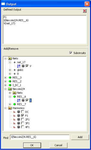
Edit Output Quantities 1. In the Circuit pulldown, select Add Solution Setup. 2. In the Solution Setup dialog, select the type of analysis to be run. Click Next. A setup dialog for the selected analysis opens. 3. In the dialog, click Edit Quantities in the Output Quantities panel. (This facility is not available for Linear Network Analysis). 4. The Output dialog opens:
For all analysis types, the Output dialog identifies the nets available for voltage outputs. After running an analysis, voltage values are available for these nodes. Expand the Nets icon to see the individual nodes. Expand each node to select its voltage as an output. For all analysis types, the Output dialog identifies devices available for current outputs. After running an analysis, current values are available for all nodes of the requested devices. For example, if you request the current through a resistor R1, the current outputs will include the values Iterminals_0(R1) and Iterminals_1(R1). For Harmonic Balance, Time-Varying Noise, and Oscillator analyses, the Output dialog identifies harmonics available for output analysis. If the circuit contains a subcircuit, the Output dialog displays its nets and devices for selection as outputs when you expand the icon for the subcircuit. 5. Click its checkbox to select an output quantity. The selected quantities are listed in the Defined Output field. 6. Click OK to close the Output dialog and return to the dialog for the selected analysis. The output quantities you selected are listed in the Output Quantities panel of the analysis dialog. Complete the solution setup as described in the topics for the individual analyses. Ports in Schematics In schematic circuit designs, you can add hierarchical ports to nodes that represent the circuit outputs. The nodes with attached ports are automatically added to the list of output quantities available for reports of simulation results. Probes in Schematics In schematic circuit designs, you can add voltage and current probes to nodes whose values are of interest. The nodes with attached probes are automatically added to the list of output quantities available for reports of simulation results. .MEASURE Quantities in Schematics A Nexxim netlist may set up a MEASURE variable to contain a value calculated during simulation. After simulation has run successfully, all variables defined in .MEASURE statements are available in the Measure Category listing of the Report dialog. See .MEASURE Statements in the File Formats topic for details.
HFSS视频教程 ADS视频教程 CST视频教程 Ansoft Designer 中文教程 |
|
Copyright © 2006 - 2013 微波EDA网, All Rights Reserved 业务联系:mweda@163.com |
|