淘宝官方店     推荐课程     在线工具     联系方式     关于我们  


微波射频仿真设计   Ansoft Designer 中文培训教程   |   HFSS视频培训教程套装


Agilent ADS 视频培训教程   |   CST微波工作室视频教程   |   AWR Microwave Office

          首页 >> Ansoft Designer >> Ansoft Designer在线帮助文档
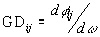
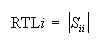
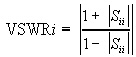
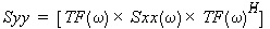
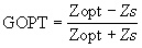
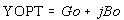
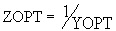
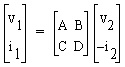
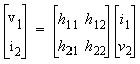
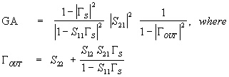
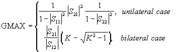
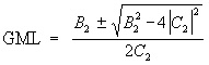
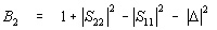
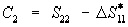
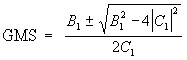
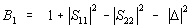
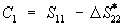
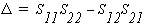
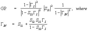
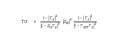
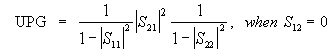
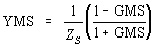
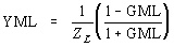
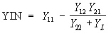
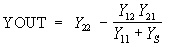
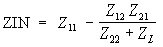
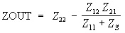
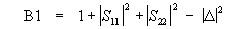
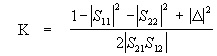
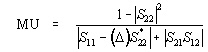
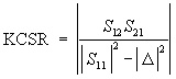
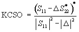
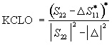
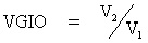
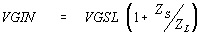
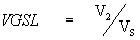

Ansoft Designer / Ansys Designer 在线帮助文档:


Nexxim Simulator >
Nexxim Linear Network Analysis >
   LNA Results       


LNA Results

The results for linear network, DC noise, and group delay analyses are summarized in the following tables. The parameters for N-ports are listed first, then the results for 2-port networks.


Netlist Parameters for N-Port Circuits

TF

Transfer function. When ports are used as described earlier, the transfer function describes the relationship between input voltage and output current.

Y

Complex Y admittance parameter matrix, I = YV

where I = vector of output currents, V = vector of input voltages

Z

Complex Z impedance parameter matrix, V = ZI

S

Complex S scattering parameter matrix, B = SA

where Ei = vector of incident waves, Er = vector of reflected waves,
V = Ei + Er, I = (Ei - Er)/Z0, Z0 = characteristic impedance,
A = Ei/Z0, B = Er/Z0

GD

Real Group Delay,

where φij=phase(Sij)


Single Port Netlist Parameters for N-Port Circuits

RHOi

Complex Reflection coefficient,

RTLi

Real Return loss

VSWRi

Real Voltage standing wave ratio,


Noise Parameters for N-Port Circuits

Onoise

N×N matrix of square roots of noise power spectra (Volt/Hz½ or Amp/Hz½).


Inoise

Input-referred noise.

FMIN

Real Minimum noise figure power ratio. FMIN is derived from fundamental noise quantities.

NF

Real Noise figure power ratio. NF is derived from fundamental noise quantities. The reference temperature for the source (port) used in NF calculations is 27 degrees Celsius.

NT

Real Equivalent noise temperature,

RN

Real Equivalent normalized noise resistance ratio. RN is derived from fundamental noise quantities.

RNU

Real Equivalent un-normalized noise resistance,

GOPT

Complex Optimum noise figure reflection coefficient,

YOPT

Complex Optimum noise figure source admittance,

where Go and Bo are derived from fundamental noise quantities.

ZOPT

Complex Optimum noise figure source impedance,


Netlist Parameters for Two-Port Circuits

ABCDij

Complex ABCD parameters (chain parameters).

Hij

Complex Hybrid parameters

Gij

Complex Inverse Hybrid parameters, G = H-1


Gain and Matching Parameters for Two-Port Circuits

GA

Available power gain,

GFMN

Gain when the input impedance (Zopt) is used to achieve minimum
noise figure (FMIN)

GMAX

Real Maximum available gain,

GML

Complex Optimum gain reflection coefficient for Load at maximum available gain (GMax),

where

and

GMS

Complex Optimum gain reflection coefficient for Source at maximum available gain (GMax), ,

where


and

GP

Power gain,

TG

Transducer power gain,

MSG

Real Maximum stable gain,

UPG

Unilateral power gain,

YMS

Source admittance at maximum available gain (GMAX),

where ZS is the source impedance.

YML

Load admittance at maximum available gain (GMAX),

where ZL is the load impedance.

ZMS

Source impedance at maximum available gain (GMAX)

ZML

Load impedance at maximum available gain (GMAX),


Port Parameters for Two-Port Circuits

YIN

Input admittance with port 2 terminated,

where YL is the load admittance.

YOUT

Output admittance with port 1 terminated,

where YS is the source admittance.

ZIN

Input impedance with port 2 terminated,

where ZL is the load impedance.

ZOUT

Output impedance with port 1 terminated,

where ZS is the source impedance.


Stability Parameters for Two-Port Circuits

B1

B1 term of the stability factor,.

where.

K

Real Stability factor k

MU

Real Stability factor mu

KCSR

Real Stability circle radius for Source,

KCLR

Real Stability circle radius for Load,

KCSO

Complex Stability circle origin for Source,

KCLO

Complex Stability circle origin for Load


Two-Port Voltage Gain Parameters

VGIO

Complex Voltage gain input-output,

VGIN

Complex Voltage gain insertion,

VGSL

Complex Voltage gain source-load,


HFSS视频教学培训教程 ADS2011视频培训教程 CST微波工作室教程 Ansoft Designer 教程

                HFSS视频教程                                      ADS视频教程                               CST视频教程                           Ansoft Designer 中文教程


      Copyright © 2006 - 2013   微波EDA网, All Rights Reserved    业务联系:mweda@163.com