|
微波射频仿真设计 |
|
|
微波射频仿真设计 |
|
| 首页 >> Ansoft Designer >> Ansoft Designer在线帮助文档 |
|
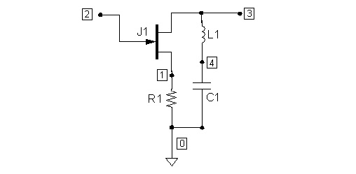
Nexxim Simulator > LNA Circuit Netlist ConfigurationIf you are using the Netlist Editor to create a design, you add the test ports to the netlist with port impedance resistors (see Resistor, Port Impedance for details). Suppose the circuit consists of the four elements in the following netlist: * JFET circuit example J1 3 2 1 njf
.MODEL njf NJF level=1 $ parameters not shown .END The corresponding schematic is diagrammed in the following figure:
To create a test port, add a port impedance resistor from an input node to ground. The port impedance resistor includes a PORTNUM parameter specifying a port number, and specifies the port impedance with parameters RZ and IZ. (see Resistor, Port Impedance in the Nexxim Component Library documentation for details on the PORTNUM, RZ, and IZ parameters.) The ZERO_PORT_VALUES=1 option tells Nexxim to treat the port resistors as external to the circuit (see LNA Options). In combination with the network analysis, Nexxim can perform an analysis of the AC small-signal transfer functions. (See LNA-Associated AC Analysis for details.) To enable AC analysis, the netlist includes one or more voltage or current sources with the AC parameter to specify the magnitude and phase of the AC value. The netlist also includes a .PRINT AC statement to specify the outputs to be analyzed.
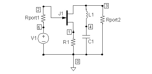
Here is the netlist with added port resistors with ZERO_PORT_VALUES option, and statements to provide for AC transfer function analysis: * JFET circuit with Port Resistors for Linear Network Analysis J1 3 2 1 njf V1 5 0 5 AC 1 0 $ Voltage source for AC analysis Rport1 2 5 PORTNUM=1 RZ=50 IZ=0 $ Port 1 impedance resistor Rport2 3 0 PORTNUM=2 RZ=50 IZ=0 $ Port 2 impedance resistor .MODEL njf NJF level=1 $ parameters not shown .LNA dec 10 5e8 5e9 flag='LNA' .OPTIONS ZERO_PORT_VALUES=1 .PRINT AC V(1) I(V1) $ Outputs for AC analysis .END The following figure diagrams the netlist as a schematic:
In a design entered with the schematic editor, the schematic would use hierarchical ports instead of the port impedance resistors, and would use a voltage probe instead of the voltage source.
HFSS视频教程 ADS视频教程 CST视频教程 Ansoft Designer 中文教程 |
|
Copyright © 2006 - 2013 微波EDA网, All Rights Reserved 业务联系:mweda@163.com |
|