|
微波射频仿真设计 |
|
|
微波射频仿真设计 |
|
| 首页 >> Ansoft Designer >> Ansoft Designer在线帮助文档 |
|
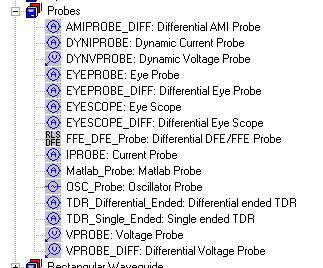
Nexxim Simulator > Add an Eye Probe for VerifEyeThe Eye Probe may be selected from the Probes list on the Components tab:
Both single-ended and differential versions are available. Right-click on the Eye Probe and select Edit Properties:
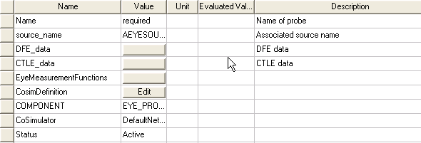
• Specify a name for the Eye Probe. • Select the Eye Source for this probe from the source_name pulldown list. • Click the DFE_data button to open the dialog:
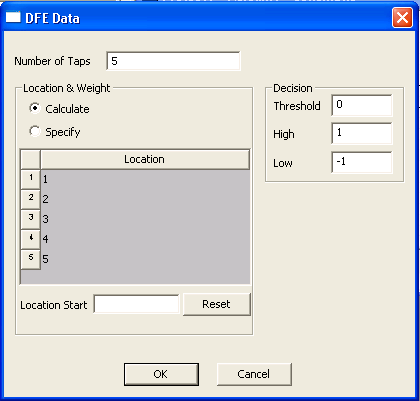
• To enable Decision-Feedback Equalization at the probe, set the Number of taps in the DFE field to a positive, non-zero value. The default is zero taps (no DFE). When one or more taps have been specified, the list of tap numbers and locations appears. • By default, Tap 1 is at location 0, the current UI. Use Location Start to set Tap 1 to a positive or negative location. Taps at positive locations are postcursors. Taps at negative locations are precursors. The location of the taps in the display change to reflect the selected starting location. (Click the Reset button to restore the default starting location.)
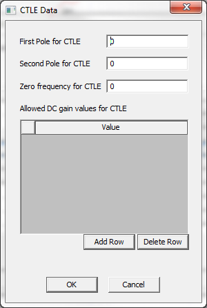
• To specify the tap weights, select Specify and enter the weights. The default is to have Nexxim calculate the weights. The algorithm always places the largest tap weight at location 0. • In addition, for DFE you can specify threshold, high, and low voltage decision levels for the equalization. The default decision threshold is 0 volts. The default high and low voltage decision levels are, +1 volt and -1 volt, respectively. • For more information on DFE, see Decision-Feedback Equalization. Click on the CTLE_data button to open the dialog:
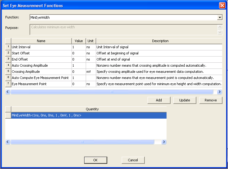
• Specify the first pole frequency in Hz (positive). The first pole frequency is the low bound of the high passband. • Optionally, specify a second pole frequency. The second pole frequency is the high bound of the passband. • Optionally, specify a zero frequency, where the response curve begins to rise. • Optionally, use the Add Row and Delete Row buttons to specify one or more allowable values for the DC gain factor in dB for the CTLE calculation. If no values are provided, Nexxim calculates the optimum CTLE gain between -infinity dB to 0 dB. • Click OK to close the CTLE Data dialog. For more information on DFE, see Continuous Time Linear Equalization. Click on the EyeMeasurementFunctions button to open the Set Eye Measurement Functions dialog:
• In the Function field, select MinEyeWidth or MinEyeHeight. • Set the Unit Interval parameter to the Unit Interval (UI) of the Eye diagram. • Set the Start Offset parameter if an initial time offset is desired. • Set the End Offset parameter if trailing time offset is desired. • Leave Auto Crossing Amplitude set to 1 (or any non-zero number) to have Nexxim compute the crossing amplitude by averaging the histograms for the high and low voltages. The crossing amplitude sets the voltage at which the minimum eye width is calculated. • When Auto Crossing Amplitude is 0, Nexxim uses the voltage set in the Crossing Amplitude parameter as the crossing voltage amplitude for the minimum eye width calculation. • Leave Auto Compute Eye Measurement Point set to 1 (or any non-zero number) to have Nexxim compute the eye measurement point by averaging the times of the crossing points. The eye measurement point sets the time at which the minimum eye height is calculated. • When Auto Compute Eye Measurement Point is 0, Nexxim uses the voltage set in the Eye Measurement Point parameter as the time for the minimum eye height calculation. • Click Add to add the measurement to the analysis. You can add any number of measurements. The dialog above has added a MinEyeWidth measurement using the default settings. • Click OK to close the Set Eye Measurement Functions dialog. Click OK to close the Properties window of the probe.
HFSS视频教程 ADS视频教程 CST视频教程 Ansoft Designer 中文教程 |
|
Copyright © 2006 - 2013 微波EDA网, All Rights Reserved 业务联系:mweda@163.com |
|