|
微波射频仿真设计 |
|
|
微波射频仿真设计 |
|
| 首页 >> Ansoft Designer >> Ansoft Designer在线帮助文档 |
|
Importing and Exporting Data > Importing ANF Design DataAnsoft Neutral File (ANF) formatted files are typically generated by third party tools or by Ansoft’s “AnsoftLinks” program that translates third-party designs. ANF is a public, neutral file format that allows third party tools to exchange design data with Ansoft products. An ANF file can contain schematic data, 2D geometry (layout), 3D geometry, and component data. None of the data is required. A given ANF file may contain just schematic data with no layout data, or may contain just layout data with no schematic data.
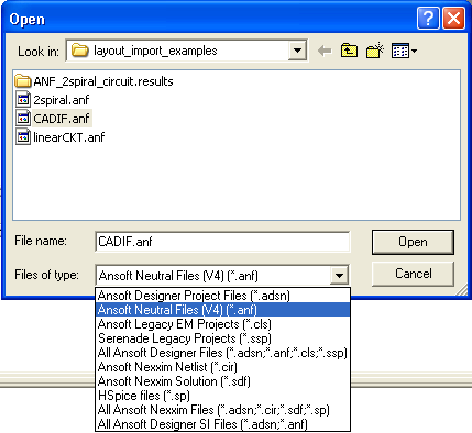
When geometry is imported from ANF, ports are automatically added, and a subdirectory for the ANF-based project is configured in the Project directory. When ANF-based projects are saved, the Save As dialog always opens, regardless of where the ANF file originated. 1. To open an ANF-based project, click File>Open on the Designer top menu bar. The File Open window opens.
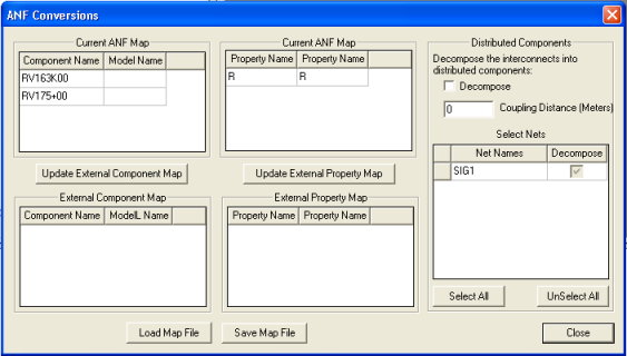
2. Use the Look in field to locate the directory containing the file with the project you want to open. Use the Files of type field to display the files with the ANF format. 3. Click on the ANF format file in the window to select it, or type its name into the File name field. 4. Click Open. The ANF Conversions dialog box opens:
5. The Current ANF (Components) Map panels list the components from the ANF file and any associated models. You can enter the names of a model manually in the Model Name field. The ModelName property for the component in Designer will be set to the entry in the Model Name field in the mapping, and the Netlist property will begin with that name instead of the component name. 6. Update External Component Map saves any mappings you enter manually to a text file. Click Save Map File to open a File Open window. Use the window to browse to the directory where the map file is to reside, then enter the name of the file. The map file is saved with a .mapping extension. The same mapping file should be used for both component and property mappings. After the mapping file has been created, Update External Component Map saves any mappings you enter manually. 7. The Current ANF (Property) Map panels list the mapping of properties in the ANF file to the properties that will be used when the file is imported. You can enter the mapped name of a property manually in the Model Name field. The name for the property in Designer will be set to the entry in the netlist. 8. Update External Property Map saves any mappings you enter manually to a text file. Click Save Map File to open a File Open window. Use the window to browse to the directory where the map file is to reside, then enter the name of the file. The map file is saved with a .mapping extension. After the mapping file has been created, Update External Component Map saves any mappings you enter manually. 9. Load Map File opens a File Open window. Use the window to browse to the directory where the map file resides, then select or enter the name of the file. The map file can contain component and/or property mappings, and must have a .mapping extension. The same mapping file should be used for both component and property mappings. 10. The External Component Map panel lists the components that have been read from an external mapping file. The display changes each time the external file is updated from the dialog. 11. The External Property Map panel lists the properties that have been read in from an external mapping file. The display changes each time the external file is updated from the dialog. 12. The Distributed Components panel allows you to specify that imported interconnects will be converted to distributed components if they fall within a minimum coupling distance (specify distance), and to select the nets that will be thus converted. The Planar EM tool will analyze the geometry intact. 13. Click Close. The Planar EM Layout Editor will show the design, and the projects window shows the imported project.
HFSS视频教程 ADS视频教程 CST视频教程 Ansoft Designer 中文教程 |
|
Copyright © 2006 - 2013 微波EDA网, All Rights Reserved 业务联系:mweda@163.com |
|